-
Question 1
5 / -1
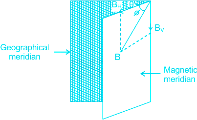
The angle between the magnetic meridian and geographic meridian is known as:
Solution
CONCEPT:
Elements of Earth's Magnetic Field:
- The magnitude and direction of the magnetic field of the earth at a place are completely given by certain quantities known as magnetic elements.
Magnetic Declination (θ)or magnetic variation:
- It is the angle between geographic and magnetic meridian planes.
- Declination at a place is expressed at θ° E or θ° W depending upon whether the north pole of the compass needle lies to the east or the west of the geographical axis.
The angle of inclination or Dip (Φ):
- It is the angle between the direction of the intensity of the total magnetic field of earth and a horizontal line in the magnetic meridian.
EXPLANATION:
- The angle of inclination or Dip is the angle between the direction of the intensity of the total magnetic field of earth and a horizontal line in the magnetic meridian.
- From above it is clear that the angle between geographic and magnetic meridian planes is known as the angle of declination or magnetic variation. Therefore option 2 is correct.
 Additional Information
- The magnetic field of the Earth along the vertical is known as the vertical component of Be.
- The magnetic field of the Earth along the horizontal is known as the horizontal component of Be.
-
Question 2
5 / -1
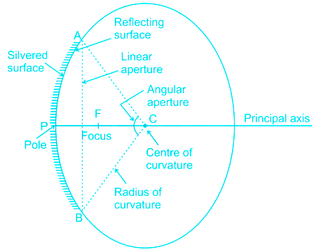
A concave mirror having a radius of curvature 40 cm is placed in front of an illuminated point source at a distance of 30 cm from it. Find the location of the image.
Solution
Concept:
- Spherical mirrors are of two types - Convex mirror, and Concave mirror.
- The image formed by the spherical mirrors depends on the position of the object.
- The relationship between the focal length (f) and the radius of curvature (R) is given by -
\(f = \frac{R}{2}\)
- Concave mirror: If the inner surface of the spherical mirror is the reflecting surface, then it is called a concave mirror. It is also called a focusing mirror/converging mirror.
- The size of the image produced by these mirrors can be larger or smaller than the object, depending upon the distance of the object from the mirror.
- The concave mirror can form both real as well as virtual images of any object.
- Mirror formula: The expression which shows the relation between object distance (u), image distance (v), and focal length (f) is called mirror formula.
\(\frac{1}{f} = \frac{1}{u} + \frac{1}{v}\)
Calculation:
Given,
Radius of curvature of concave mirror (R) = -40 cm
So focus = R/2 = -40/2 = -20 cm
Object is placed in front of mirror (u) = -30 cm
Image position (v) =?
We know that,
\(\frac{1}{f} = \frac{1}{u} + \frac{1}{v} \Rightarrow \frac{1}{v} = \frac{1}{f} - \frac{1}{u}\)
\( \Rightarrow \frac{1}{v} = \frac{1}{{ - 20}} - \frac{1}{{ - 30}} = \frac{{ - 3 + 2}}{{60}} = - \frac{1}{{60}}\)
\(\frac{1}{v} = - \frac{1}{{60}} \Rightarrow v = - 60\;cm\)
The image is formed at 60 cm in front of mirror or on the side of object.
-
Question 3
5 / -1
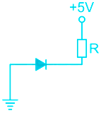
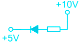
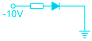
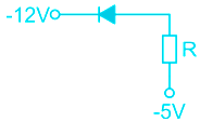
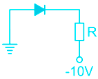
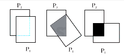
In the given figure, which of the diodes are forward biased?
1. 
2. 
3. 
4. 
5. 
Solution
CONCEPT:
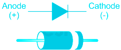
- Diode: A diode is a two-terminal electronic component that conducts current primarily in one direction; it has low resistance in one direction, and high resistance in the other.
There are two
- Forward Biasing:
- The forward bias means the positive region is connected to the p-terminal of the supply and the negative region is connected to the n-terminal of the supply.
- In forward biasing the external voltage is applied across the PN-junction diode.
- Reverse Biasing:
- In reversed bias, the negative region is connected to the positive terminal of the battery and the positive region is connected to the negative terminal.
- It creates a high resistive path in which no current flows through the circuit.
EXPLANATION:
- The forward bias means the positive region is connected to the p-terminal of the supply and the negative region is connected to the n-terminal of the supply.
- Therefore from the above figure, it is clear that P-crystals are more positive as compared to N-crystals in the case of figures 2, 5, and 4. Hence option 4 is correct.
-
Question 4
5 / -1
Numerical values of the momentum and kinetic energy of a particle are equal. Velocity of the particle is:
Solution
Concept:
- Kinetic energy (K.E): The energy possessed by a body by the virtue of its motion is called kinetic energy.
The expression for kinetic energy is given by:
\(KE = \frac{1}{2}m{v^2}\)
Where m = mass of the body and v = velocity of the body
- Momentum (p): The product of mass and velocity is called momentum.
Momentum (p) = mass (m) × velocity (v)
The relationship between the kinetic energy (KE or k) and Linear momentum is given by:
As we know,
\(KE = \frac{1}{2}m{v^2}\)
Divide numerator and denominator by m, we get
\(KE = \frac{1}{2}\frac{{{m^2}{v^2}}}{m} = \frac{1}{2}\frac{{\;{{\left( {mv} \right)}^2}}}{m} = \frac{1}{2}\frac{{{p^2}}}{m}\;\) [p = mv]
\(\therefore KE = \frac{1}{2}\frac{{{p^2}}}{m}\;\)
\(p = \sqrt {2mKE} \)
Calculation:
Let, m be the mass of the body and v be the velocity of the body.
Now, momentum of the body is
p = mv
Kinetic energy is
\(KE = \frac{1}{2}m{v^2}\)
As per given condition,
Say,
\(Momentum = Kinetic\;energy = x\)
\(\Rightarrow mv= {1\over2}mv^2=x\)
\(\Rightarrow {1\over2}mv^2=x\)
\(\Rightarrow {1\over2m}m^2v^2=x\)
we know (mv)2 = x2
\(\Rightarrow {1\over2m}x^2=x\)
\(\Rightarrow x=2m\)
\(\Rightarrow mv=2m \Rightarrow v=2\)
Hence the correct answer is 2 m/s.
-
Question 5
5 / -1
Consider the following the statements
1. Meter bridge works on the principal of the Wheatstone bridge.
2. A Meter bridge is used to find the unknown resistance.
3. A meter bridge is used to find the internal resistance of the battery.
Which of the following statement is INCORRECT?
Solution
CONCEPT:
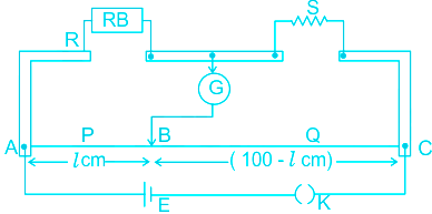
- Meter bridge: Meter bridge is instruments based on the principle of Wheatstone bridge and is used to measure an unknown resistance.
- In the case of a meter bridge, the resistance wire AC is 100 cm long. Varying the position of tapping point B, the bridge is balanced.
- If in the balanced position of bridge AB = l, BC (100 – l) so that
\(\frac{Q}{P} = \frac{{\left( {100 - l} \right)}}{l}\)
Also, \(\frac{P}{Q} = \frac{R}{S} \Rightarrow S = \frac{{\left( {100 - l} \right)}}{l}R\)
EXPLANATION:
- From above it clear that the meter bridge works on the principle of Wheatstone bridge. Therefore, option 1 is correct.
- The Meter Bridge is instruments based on the principle of Wheatstone bridge and is used to measure an unknown resistance. Therefore option 2 is correct.
- The Meter bridge can't measure the internal resistance of a battery.
- A potentiometer is a device used to measure the internal resistance of the battery. Therefore option 3 is incorrect.
-
Question 6
5 / -1
The potential energy of two non-zero point charges is assumed to be zero when they are at an infinite distance apart. The potential energy of these two point charges when they are at a finite distance is:
Solution
CONCEPT:
- Force one a charge q in an electric field is defined as
⇒ F = Eq
- The work done by this force in moving the charge by a distance d along the direction of electrostatic force (along the electric field) is
⇒ W = F.d = Eq.d
- The work done by external force in moving this charge by a distance d along the direction of the electrostatic field is
⇒ Wext = - W = - Eq.d
- By definition, the change in potential energy in moving the charge in an electrostatic field is equal to the work done by external forces
\(\Rightarrow \bigtriangleup U = W_{ext} = -Eq.d\)
- Electric potential is equal to the amount of work done per unit charge by an external force to move the charge q from infinity to a specific point in an electric field
\(\Rightarrow V=\frac{W_{ext}}{q}\)
- Therefore the relation between electric potential and electric potential energy is given by
\(\Rightarrow \bigtriangleup U = W_{ext} = Vq\)
EXPLANATION:
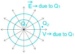
- The potential energy of the system is due to the interaction between Q1 and Q2
\(\Rightarrow U = Vq = (\frac {Q_1 }{4 \pi \epsilon_0R_{12}} )Q_2\)
- If Q1 and Q2 have the same sign, the potential energy is positive. Therefore option 1 is correct.
-
Question 7
5 / -1
The appearance of Sun is ____________ at sunrise and sunset.
Solution
Concept:
- Scattering of light: The phenomenon in which the light ray is redirected in all other directions on passing through particles of dimensions comparable to the wavelength of the light used is called scattering of light.
- Rayleigh scattering: The scattering of light off of the molecules of the air that can be extended to scattering from particles up to about a tenth of the wavelength of the light used is called Rayleigh scattering.
\(Intensity\;of\;scattered\;light\;\left( I \right) \propto \;\frac{1}{{{\lambda ^4}}}\)
Where λ is the wavelength of light
Explanation:
- At the time of sunset and sunrise, the sun is farther from the earth.
- The sun’s rays have to pass through a larger distance in the atmosphere.
- The shorter wavelengths get scattered by particles in air.
- So the light with a higher wavelength (like red) reaches our eyes.
So, the sun appears reddish during sunrise and sunset.
Additional Information Our sky appears blue due to the scattering of light. The blue light scattered the most due to less wavelength.
-
Question 8
5 / -1
Nuclides having the same atomic and mass numbers are known as:
Solution
CONCEPT:
Isotope:
- Isotopes can be defined as the variants of chemical elements that possess the same number of protons and electrons, but a different number of neutrons.
- For example, carbon-14, carbon-13, and carbon-12 are all isotopes of carbon. Carbon-14 contains a total of 8 neutrons, carbon-13 contains a total of 7 neutrons, and carbon-12 contains a total of 6 neutrons.
Isobars:
- The atoms have the same number of nucleons. Isobars of different chemical elements have different atomic numbers but have the same mass number.
Isotones:
- Isotones are atoms that have the same neutron number but different proton number.
Isomers:
- Nuclides having the same atomic and mass numbers are known as Isomers.
EXPLANATION:
- From the above, it is clear that nuclides having the same atomic and mass numbers are known as Isomers. Hence, option 1 is correct.
-
Question 9
5 / -1
Pick the incorrect statement from the following
Solution
The correct answer is option 3) i.e. Electric flux is a vector quantity
CONCEPT:
- Electric flux: It is the number of electric field lines passing through a given surface area.
The electric flux associated with a surface kept in a uniform electric field is given by:
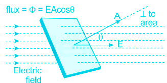
ϕ = E.A = EAcosθ
Where E is the uniform electric field, A is the area of the surface and θ is the angle between E and the area vector of A.
EXPLANATION:
Electric flux, ϕ = E.A and thus it is dependent on the intensity of the electric field.
- The electric flux ϕ will be maximum when cosθ = 1 i.e. θ = 0∘. This is possible by placing the plane surface perpendicular to the electric field.
- Electric flux is the dot product of two vector quantities i.e. electric field and area vector. Hence, it is a scalar quantity.
Hence, option 3) is an incorrect statement.
-
Question 10
5 / -1
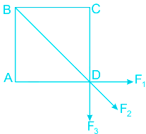
When the frequency applied to a series LRC circuit is increased, the impedance of the circuit:
Solution
Concept:
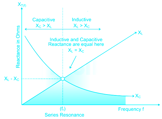
- In an electrical circuit, the condition that exists when the inductive reactance and the capacitive reactance are of equal magnitude, causing electrical energy to oscillate between the magnetic field of the inductor and the electric field of the capacitor, is termed as resonance.
- In a series RLC circuit at resonance, inductive reactance (XL) is equal to capacitive reactance (XC). The circuit becomes purely resistive, i.e. at resonance: XL = XC
The impedance at resonance becomes:
\(Z = \sqrt {{R^2} + {{\left( {{X_L} - {X_C}} \right)}^2}} = R\)
- The impedance - frequency curve is shown below:
Explanation:
So, from the above graph
- The impedance and current depend upon the frequency (f). As f is increased ωL is increased, \(x = {1\over (\omega C)}\)is decreased.
- At resonance the impedance is minimum.
So, the frequency applied to a series LRC circuit is increased, the impedance of the circuit first decreases and then increases after reaching a minimum value.
-
Question 11
5 / -1
The angle between the electric field due to dipole on its axial line and the equatorial line is:
Solution
CONCEPT:
- Electric dipole: When two equal and opposite charges are separated by a small distance then this combination of charges is called an electric dipole.
- The multiplication of charge and the distance between them is called as electric dipole moment.
- The electric dipole moment is denoted by P and the SI unit of dipole moment is Coulombmeter (Cm)
Dipole moment = P = q × d
Where q is charge and d is the distance between two charged particles.
- The direction electric dipole moment is from negative charge to positive charge.
EXPLANATION:
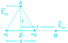
- The magnitude of the electric field of a short dipole at an axial point at a distance of r from its center is
\({E_{axial}} = \frac{{2kp}}{{{r^3}}}\) ------ (1) [ E and P are parallel to each other ]
- From the above diagram, it is clear that the direction of the electric field (E) is along with PB i.e., along the direction of the electric dipole moment (p). Hence the angle between the electric fields due to dipole on its axial line is 0°.
- The magnitude of the electric field of a short dipole at an equatorial point at a distance r from its center is
\({E_{equi}} = \frac{{kp}}{{{r^3}}}\) ------ (2) [ E and P are antiparallel to each other ]
- From the above diagram, it is clear that the direction of the electric field (E) is in the opposite direction of the electric dipole moment (p). Hence the angle between the electric fields due to dipole on its axial line is 180°.
- Hence, option 3 is the answer
-
Question 12
5 / -1
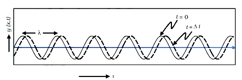
The phase difference in electric and magnetic force fields of an electromagnetic wave is-
Solution
Concept:
Electromagnetic waves (EM Waves)
- The electromagnetic wave is a special kind of wave which do not require any material medium for its propagation.
- The EM wave is a combination of the time-varying oscillating electric and magnetic field which propagates in a space with a speed very closed to the speed of light.
- It is also called the EM wave.
- EM waves are formed when the electric and magnetic field comes in contact and oscillates perpendicular to each other.
- The direction of propagation of EM is perpendicular to that of the oscillating electric and magnetic field.
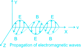
Here E is electric field, B is magnetic field.
Explanation:
Peaks of magnetic and electric waves of electromagnetic waves form at the same time. Hence, there is no phase difference between these two waves.
Therefore the phase difference between them is 0
The correct option is 0.
-
Question 13
5 / -1
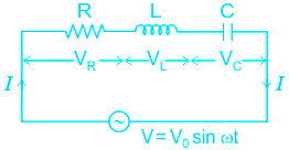
In the given circuit, assuming point A to be at zero potential, use Kirchhoff’s rules to determine the potential at point B.
Solution
CONCEPT:
Kirchhoff’s Law: Kirchhoff's circuit laws are two equalities that deal with the current and potential difference. They were first described in 1845 by German physicist Gustav Kirchhoff.
Kirchhoff’s Current Law (KCL): The algebraic sum of currents at any node of a circuit is zero. It can be described as also, the total current enters is exactly equal to the total current leaves the point.
It is also known as Kirchhoff’s first law.
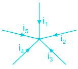
i1 + i2 + i3 + i4 + i5 = 0
Kirchhoff’s Voltage Law (KVL): The algebraic sum of voltage (or voltage drops) in any closed path of a network in a single direction is zero.
It is also known as Kirchhoff’s second law.
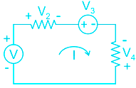
V – V2 – V3 + V4 = 0
V + V4 = V2 + V3
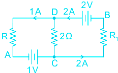
Calculation:
Applying KCL at point D in the given circuit
i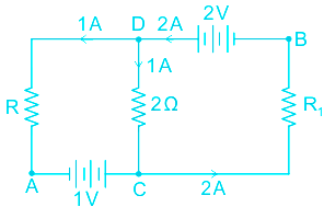
By Kirchhoff’s law at D
IDC = 1 A (IDC + 1 = 2)
Applying KVL along the path ACDB,
VA + 1 + 1 × 2 – 2 = VB
But VA = 0,
VB = 1 + 2 – 2 = 1 V
VB = 1 V
So option 3 is correct.
-
Question 14
5 / -1
The electric field intensity at a point due to a uniformly charged infinite plane sheet depends on the:
Solution
CONCEPT:
Gauss law:
- According to the Gauss law, the total flux associated with any closed surface is 1/ε0 times the total charge enclosed by the closed surface.
\(\Rightarrow ϕ=\int \vec{E}.\vec{dA}=\frac{q}{ϵ_{o}}\)
Electric field intensity due to a uniformly charged infinite plane sheet:
- The electric field intensity at a point due to a uniformly charged infinite plane sheet is given as,
\(\Rightarrow E=\frac{σ}{2ϵ_o}\)
Where σ = surface charge density, and ϵo = permittivity
- The electric field intensity due to a uniformly charged infinite plane sheet does not depend on the distance of the point from the plane sheet.
EXPLANATION:
- We know that the electric field intensity at a point due to a uniformly charged infinite plane sheet is given as,
\(\Rightarrow E=\frac{σ}{2ϵ_o}\) ---(1)
Where σ = surface charge density, and ϵo = permittivity
- By equation 1 it is clear that the electric field intensity due to a uniformly charged infinite plane sheet depends on the surface charge density only. Hence, option 1 is correct.
-
Question 15
5 / -1
When the current flowing in a circular coil is doubled and the number of turns in it is halved, the magnetic field at its center will become -
Solution
Concept:
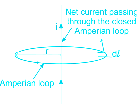
Ampere’s Circuital Law
It states that the integrated magnetic field B along an imaginary closed path is equal to the multiplication of net electricity current enclosed inside this path and permeability of the medium.
\(\oint \overrightarrow{B}.\overrightarrow{dl} = μ _{0} I\)
where is B is the magnetic field μ0 magnetic permeability, I is current enclosed, dl is the length.
The law is used to find Fields due to current-carrying straight wire, circular wire, solenoid etc.
Field Due to Current Carrying wire with N turns
\( B = \frac{\mu _{0} NI}{2 R}\) -- (1)
N is a number of turns, I is current, R is the radius of the loop
Calculation:
The number of turns is doubled, the new number of turns N' = 2N
Current is halved, the new current I' = I / 2
The new field
\( B' = \frac{\mu _{0} N'I'}{2 R} = \frac{\mu _{0} 2NI/2}{2 R}\)
\(\implies B' = \frac{\mu _{0} NI}{2 R} = B\) (Using 1)
So, B' = B
There is no change in the magnetic field.
So, the correct option is same.
-
Question 16
5 / -1
Which among the following statements is true about Huygen's principle
Solution
The correct answer is option 1) i.e. Each point in a wavefront is a source of secondary waves.
CONCEPT:
Huygens' concepts of secondary wavelets:
- Huygen’s principle states that every point on the wavefront may be considered as a source of secondary spherical wavelets that spread out in the forward direction at the speed of light.
- The new wavefront is the tangential surface of all these secondary wavelets.
- Secondary sources start making their own wavelets, these waves are similar to that of the primary source
- It states that each point on a wavefront is a source of wavelets, which spread forward with the same speed.
- Wavefront: A wavefront is a surface or a line on which the disturbance at every point has the same phase.
- Wavelets: It is a wave-like oscillation with an amplitude that starts at zero, increases, and then decreases back to zero.
EXPLANATION:
- Huygens's principle states that each point on a wavefront is a source of wavelets, which spread forward with the same speed.
-
Question 17
5 / -1
The magnifying powers of objective lens and eyepiece lens of a compound microscope are 10 and 20 respectively. Its resultant magnifying power will be
Solution
CONCEPT:
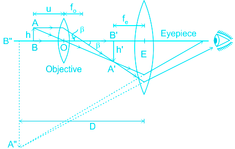
Compound microscope:
- A compound microscope is an optical instrument that is used to obtain highly magnified images.
- It uses a set of two lenses
- Eyepiece lens
- Objective lens.
- Generally, the eyepiece used is of lower power than that of the objective lens.
- A typical working of the compound microscope is as shown
- Magnification of a compound microscope (m) is given by the formula
⇒ m = mo × me
Where mo is the magnifying power of the objective lens and me is the magnifying power of the eyepiece.
CALCULATION:
Given - Magnifying power of an objective lens (mo) = 10 and the magnifying power of the eyepiece lens (me) = 20
- Magnification of a compound microscope (m) is:
⇒ m = mo × me
⇒ m = 10 × 20 = 200
-
Question 18
5 / -1
The magnetic flux linked with a coil in weber is given by the equation ϕ = 6t2 + 3t + 2. Then the magnitude of induced emf in the coil at t = 3 sec will be:
Solution
CONCEPT:
Faraday's first law of electromagnetic induction:
- Whenever a conductor is placed in a varying magnetic field, an electromotive force is induced.
- If the conductor circuit is closed, a current is induced which is called induced current.
Faraday's second law of electromagnetic induction:
- The induced emf in a coil is equal to the rate of change of flux linked with the coil.
\(⇒ e=-N\frac{dϕ}{dt}\)
Where N = number of turns, dϕ = change in magnetic flux and e = induced e.m.f.
- The negative sign says that it opposes the change in magnetic flux which is explained by Lenz law.
CALCULATION:
Given - ϕ = 6t2 + 3t + 2 and t = 3 sec
Magnetic flux linked with a coil is given as
⇒ ϕ = 6t2 + 3t + 2
\(⇒ \frac{dϕ}{dt}=\frac{d}{dt}(6t^2+3t+2)\)
\(⇒ \frac{dϕ}{dt}=12t+3\) -----(1)
So induced emf is given as,
\(⇒ e=\frac{dϕ}{dt}\)
⇒ e = 12t +3 -----(2)
Induced emf at t = 3 sec,
⇒ e = 12 × 3 +3
⇒ e = 39 V
-
Question 19
5 / -1
In a common emitter amplifier the input signal is applied across
Solution
CONCEPT:
- Amplifier: An electronic device that is mainly used to increase the amplitude of electrical signals, is called an amplifier.
- In Common emitter configuration (CE) emitter is the common terminal.
- The following diagram shows an amplifier with a common emitter.
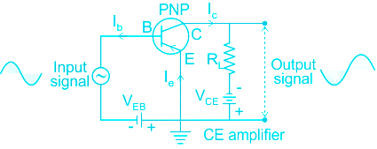
wherein the diagram notations E- emitter, C- Collector, B- base, I- current, V- voltage.
EXPLANATION:
- From the diagram of the common emitter amplifier,
- When we put an amplifier with a common emitter, the input is applied to the base.
- The output is taken from the collector.
- So the correct answer is option 3.
-
Question 20
5 / -1
The particle required to continue the chain process of Uranium fission is ________
Solution
CONCEPT:
- The nucleus of a heavy atom (such as uranium, plutonium or thorium), when bombarded with low-energy neutrons, can be split apart into lighter nuclei. This process is called nuclear fission.
- Fission occurs when a neutron slams into a larger atom, forcing it to excite and split into two smaller atoms—also known as fission products.
- A chain reaction refers to a process in which neutrons released in fission reaction produces an additional fission reaction in at least one further nucleus. This nucleus, in turn, produces neutrons, and the process repeats.
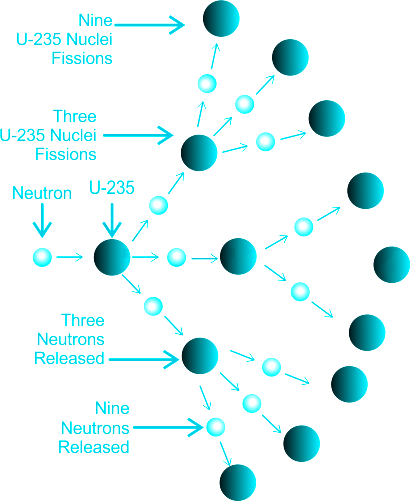
- During this reaction, a tremendous amount of energy is released.
EXPLANATION:
- Nuclear chain reactions are a series of nuclear fission (splitting of atomic nuclei), each initiated by a neutron produced in a preceding fission. So option 3 is correct.
- For example, 2.5 neutrons on an average are released by the fission of each uranium-235 nucleus that absorbs a low-energy neutron.
-
Question 21
5 / -1
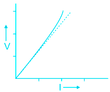
Ohm's law is not valid when
Solution
CONCEPT:
Ohm's law:
- A conductor through which a current I is flowing and let V be the potential difference between the ends of the conductor. Then Ohm’s law states that
⇒ V ∝ I
⇒ V = IR
where R is called the resistance of the conductor. Resistance depends on the shape, size, and material of the conductor.
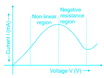
Limitations of Ohm's law:
- Ohm’s law is valid over a large class of materials.
- There do exist materials and devices used in electric circuits where the proportionality of V and I does not hold.
The deviations in occurring are one or more of the following types:
- V is not to be proportional to I for some range of V or I
- The relation between V and I depends on the sign of V.
- Reversing the direction of V keeping its magnitude fixed does not produce a current of the same magnitude as I in the opposite direction.
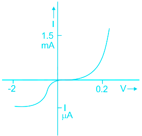
- The relation between V and I is not unique
- There is more than one value of V for the same current I
EXPLANATION:
Ohm's law:
- A conductor through which a current I is flowing and let V be the potential difference between the ends of the conductor. Then Ohm’s law states that
⇒ V ∝ I
⇒ V = IR
where R is called the resistance of the conductor. Resistance depends on the shape, size, and material of the conductor.
- The above equation is that of a straight line, where the slope is constant and is equal to R.
- Ohm's law will not be valid if the slope of the equation is variable.
- Meaning Ohm's law will not be valid if the rate of change of potential with respect to current is variable. Therefore option 2 is correct.
-
Question 22
5 / -1
The wave nature of electrons was first proved by whom?
Solution
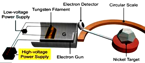
The correct answer is Davison and Germer experiment.
- The Davisson and Germer experiment demonstrated the wave nature of the electrons, confirming the earlier hypothesis of de Broglie.
- Electrons exhibit diffraction when they are scattered from crystals whose atoms are spaced appropriately.
- Putting wave-particle duality on a firm experimental footing, represented a major step forward in the development of quantum mechanics.
- Davisson and Germer designed and built a vacuum apparatus for the purpose of measuring the energies of electrons scattered from a metal surface.
- Electrons from a heated filament were accelerated by a voltage and allowed to strike the surface of nickel metal.
Apparatus of Davisson and Germer experiment
Additional Information
| Experiment | Description |
| Photoelectric effect | The photoelectric effect is often defined as the ejection of electrons from a metal plate when light falls on it. |
| Double slit experiment | It suggests that what we call "particles", such as electrons, somehow combine characteristics of particles and characteristics of waves. |
| Compton effect | The Compton effect (also called Compton scattering) is the result of a high-energy photon colliding with a target, which releases loosely bound electrons from the outer shell of the atom or molecule. |
-
Question 23
5 / -1
A rectangular current carrying loop is placed in a uniform magnetic field of magnitude B. The angle between the plane perpendicular to the coil and the magnetic field is θ. The current in the loop is I. Then the torque on the rectangular loop will be-
Solution
CONCEPT:
- As the current-carrying conductor experiences a force when placed in a magnetic field, each side of a current-carrying rectangular coil experiences a force in a magnetic field.
- In the present section, we shall see in what way the rectangular loop carrying current is influenced by a magnetic field.
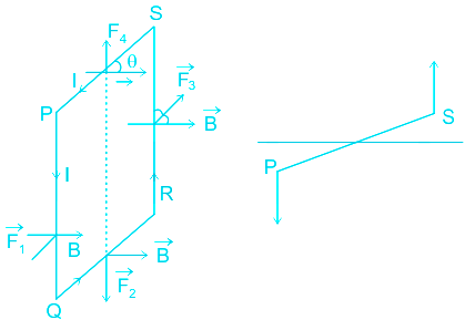
- Consider a rectangular coil of length l and breadth b carrying a current I placed in a uniform magnetic field B.
- θ, be the angle between the plane of the rectangular coil and the magnetic field.
Force acting on the rectangular loop:
F = I L B sinθ, where F is force, I = current, L = distance from the axis, B = strength of the magnetic field, θ = angle between the plane of the rectangular coil and the magnetic field.
- Acting on the upper and lower sides are equal and opposite along the same line of action, they cancel each other.
- As the force acting on the sides QR and SP are equal and opposite along different lines of action they constitute a couple.
So, the torque acting on the loop is,
T = force × arm of the couple
T = B I L × b Sinθ = B I A Sinθ
T = B I A Sinθ
EXPLANATION:
- The torque acting on the rectangular loop is
T = B I A sin θ.
So option 2 is correct.
-
Question 24
5 / -1
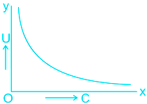
The following graph shows variation of total energy U stored in a capacitor against the value of its capacitance C. Which of the following parameter is constant?
Solution
The correct answer is option 1) i.e. Charge Q
CONCEPT:
- Capacitor: A capacitor is an electrical component with two terminals used to store charge in the form of an electrostatic field in it.
- It consists of two parallel plates each possessing equal and opposite charges, separated by a dielectric constant.
- Capacitance is the ability of a capacitor to store charge in it. The capacitance C is related to the charge Q and voltage V across them as:
\(C = \frac{Q}{V}\)
- Electrostatic energy stored in a capacitor:
- When a capacitor is getting charged, the charge builds on the plates slowly and reaches the maximum value Q. This happens as a small charge dQ moves from one plate to the other under the influence of applied voltage V.
- Therefore, work done in moving dQ charge, dW = V × dQ
- The total work done to acquire the charge from 0 to Q,
\(⇒ W = ∫dW =\int^Q_0V× dQ = \int^Q_0\frac{Q}{C}dQ \) (∵ C = \(\frac{Q}{V}\) ⇒ V = \(\frac{Q}{C}\))
\(⇒ W =\frac{1}{C} [\frac{Q^2}{2}]^Q_0 = \frac{Q^2}{2C}\)
This work done is nothing but the electrostatic energy stored in a capacitor.
Hence, electrostatic energy in a fully charged capacitor, \(U=\dfrac{Q^2}{2C}\)
EXPLANATION:
From the graph, it is inferred that \(U ∝ \frac{1}{C}\).
Electrostatic energy stored, \(U=\dfrac{Q^2}{2C} = \frac{(CV)^2}{2C}=\frac{CV^2}{2}\) (∵ \(C = \frac{Q}{V} \Rightarrow Q = CV\))
- If V were constant, U ∝ C. Then the U vs C graph should be a straight line.
If Q is constant, \(U ∝ \frac{1}{C}\) as shown in the graph.
Thus, Q is constant.
-
Question 25
5 / -1
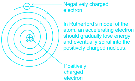
What are the limitations of Rutherford’s model of an atom-?
Solution
CONCEPT:
- Rutherford’s Model of the Atom:
- He bombarded the beam of alpha particles on a very thin gold foil.
- While bombarding he observes the number of scattering of particles –
- Most of the particles passed either un-deviated or with very small deviation.
- Some deviated by large angles
- 1 out of 8000 was deflected by more than 90°
- Conclusion to this deflection:
- Most of the space of an atom is empty.
- At the center of an atom having a tiny positively charged particle called a nucleus.
- The center nucleus has all the mass of an atom.
- The amount of positive charge at the nucleus is equal to the total amount of negative charges on all the electrons of the atom.
- All the electrons revolve around the nucleus and coulomb force provide centripetal force
Limitations of Rutherford’s Model of the Atom:
- As Rutherford’s Model suggests electrons always revolve around the nucleus.
- From the point of mechanics it is okay as Coulomb force provides the necessary centripetal force.
- But Maxwell’s equation of electromagnetism show any accelerated electron must continuously emit electromagnetic radiation.
- This revolving electron continuously emit radiation at all temperature.
- This energy spend ultimately makes an electron to fall on the nucleus.
- But in real case hydrogen is very stable nor emit any energy.
EXPLANATION:
- According to Maxwell’s equation of electromagnetism, an accelerated electron must continuously emit electromagnetic radiation and loses its energy and fall towards the nucleus.
- Thus Rutherford model can’t explain this loss of energy. Therefore option 3 is correct.
-
Question 26
5 / -1
Why amplification of a signal is necessary in a communication system?
Solution
CONCEPT:
- Amplification: It is the process of increasing the amplitude and strength of an electrical signal with the help of an amplifier usually a transistor amplifier. Amplification is important to compensate for the loss of strength during its transmission across the channel. It is done at the point in the channel where the strength of the signal becomes weakened.
- Attenuation: It is the loss of strength of a signal during its transmission across the communication channel.
EXPLANATION:
- During transmission of signals, the strength of the signal becomes weak and in that case, amplification is required to compensate for this loss of strength or attenuation.
- The correct answer is option (1)
-
Question 27
5 / -1
Nucleus of He is revolving in circular orbit of radius 0.8 m. It completes a circle in 2 seconds, then the magnetic induction at the centre of circle is:
Solution
CONCEPT:
- The nucleus of He: The nucleus of He consist of two protons and two neutrons.
- Magnetic field: A magnetic field is a vector field in the neighborhood of a magnet, electric current, or changing electric field, in which magnetic forces are observable.
- Magnetic field intensity: Magnetic field intensity at any point in the magnetic field is defined as the force experienced by the unit north pole at that point.
- Magnetic field intensity at the center of the current-carrying circular loop is given as,
\(\Rightarrow B=\frac{\mu_{o}NI}{2r}\) -----(1)
Where B = Magnetic field intensity, N = number of llops, I = current and r = radius
CALCULATION:
Given Q = 2×1.6×10-19 C, r = 0.8 m, N = 1 and T = 2 sec
Current,
\(\Rightarrow I=\frac{Q}{T}=\frac{2\times1.6\times10^{-19}}{2}\)
\(\Rightarrow I=1.6\times10^{-19}A\)
- The magnetic induction at the centre of circle is:
\(\Rightarrow B=\frac{\mu_{o}NI}{2r}\)
\(\Rightarrow B=\frac{4\pi\times10^{-7}\times1\times1.6\times10^{-19}}{2\times0.8}\)
\(\Rightarrow B=4\pi\times10^{-26}T\)
- Hence, option 1 is correct.
-
Question 28
5 / -1
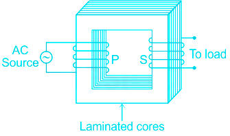
The ratio of the number of turns in secondary and primary coils of a step up transformer is 4 : 1. If the current in the primary coil is 4 amp. The current in the secondary coil is:
Solution
CONCEPT:
- A Transformer is used to convert low voltage (or high current) to high voltage (or low current) and high voltage to low voltage.
- It works on the principle of electromagnetic induction.
- The primary coil has Np turns and the other coil, called the secondary coil, has Ns turns.
- Generally, the primary coil works as the input coil and the secondary coil works as the output coil of the transformer.
- In a transformer, the voltage in secondary is calculated by
\(\Rightarrow \frac{N_{s}}{N_{p}}=\frac{V_{s}}{V_{p}}=\frac{i_p}{i_s}\)
Where, Np and Ns are the numbers of turns in the primary and secondary coils respectively,Vp and Vs are the rms voltages across the primary and secondary respectively, ip and is are the current in the primary and secondary coil.
- In a transformer, the load is connected to the secondary coil while the primary coil of a transformer is connected to an AC source.
EXPLANATION:
Given - Ns : Np = 4 : 1 and Ip = 4 A
- The current in the secondary coil is:
\(\Rightarrow i_s={i_p}\times \frac{N_{p}}{N_{s}}=4\times \frac{1}{4}=1 \, A\)
-
Question 29
5 / -1
Current in a coil changes from 4 A to zero in 0.1 second and the emf induced is 100 V. The self inductance of the coil is
Solution
The correct answer is option 2) i.e. 2.5 H.
CONCEPT:
- Self-inductance: Self-inductance is the phenomenon where a current-carrying coil resists the change in the current flowing through it.
- The resistance to the change in current is due to the induced emf in the coil.
- The direction of the induced emf is opposite to the applied voltage if the current is increasing and the direction of the induced emf is in the same direction as the applied voltage if the current is decreasing.
- The unit of inductance is Henry (H).
The induced emf is related to the change in current as follows:
\(e = - L \frac{di}{dt}\)
Where e is the induced emf, L is the self-inductance of the coil, and di/dt is the rate of change of current in the coil.
CALCULATION:
Given that:
Change in current, \(di\) = (0 - 4) A
Time interval, \(dt\) = 0.1 s
Induced emf, e = 100 V
Using \(e = - L \frac{di}{dt}\)
\(100 = -L (\frac{0-4}{0.1})\)
\(L = \frac{10}{4}\)
Self-inductance, L = 2.5 H
 Mistake Points
- Here, the current is changing from 4 A to 0 A i.e. current is falling. Therefore, change in current = (final - initial) current = (0 - 4) A
-
Question 30
5 / -1
Nature of which of the following rays is not electromagnetic?
Solution
CONCEPT:
- Electromagnetic spectrum: The complete range of light that exists in nature is called an electromagnetic spectrum.
- The waves that are created as a result of vibrations between an electric field and a magnetic field is called Electromagnetic waves.
- The waves of the electromagnetic field, propagating through space and carrying electromagnetic radiant energy is called electromagnetic radiation.
- It consists of radio waves, microwaves, infrared, light, ultraviolet, X-rays, and gamma rays.
EXPLANATION:
- From the above, it is clear that alpha ray, also called alpha particles alpha ray, contains two protons and two neutrons bound together into a particle just like a helium-4 nucleus, and it not an electromagnetic rays.
-
Question 31
5 / -1
To obtain an enlarged real inverted image beyond 2F2 after refraction by convex lens, where should the object be placed?
Solution
CONCEPT:
- Lens: The transparent curved surface which is used to refract the light and make an image of any object placed in front of it is called a lens.
- Convex lens: A lens having two spherical surfaces, bulging outwards is called a double convex lens (or simply convex lens).
- It is thicker in the middle as compared to the edges.
- Convex lenses converge light rays and hence, convex lenses are also called converging lenses.
EXPLANATION:
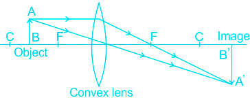
- To obtain an enlarged real inverted image beyond 2F2 after refraction by a convex lens, the object should be placed between F1 and 2F1. So option 2 is correct.
EXTRA POINTS:
- Nature, position, and relative size of the image formed by a convex lens for various positions of the object:-
Position of the object | Position of the image | The relative size of the image | Nature of the image |
At infinity | At focus F2 | Highly diminished, point-sized | Real and inverted |
Beyond 2F1 | Between F2 and 2F2 | Diminished | Real and inverted |
At 2F1 | At 2F2 | Same size | Real and inverted |
Between F1 and 2F1 | Beyond 2F2 | Enlarged | Real and inverted |
At focus F1 | At infinity | Infinitely large or highly enlarged | Real and inverted |
Between focus F1 and optical center O | On the same side of the lens as the object | Enlarged | Virtual and erect
|
NOTE:
- 2F1 is centre of curvature (C) on the left side of the lens and 2F2 is centre of curvature (C) on the right side of the lens.
-
Question 32
5 / -1
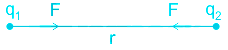
The four equal charge particles of charge q are placed at the corners of a square of side a. Find the net electrostatic force on any one charge particle (Here K = 1/(4π ϵ0)).
Solution
CONCEPT:
- Coulomb’s law: When two charge particles of charges q1 and q2 are separated by a distance r from each other then the electrostatic force between them is directly proportional to multiplication of charges of two particles and inversely proportional to square of distance between them.
Force (F) ∝ q1 × q2
\(F \propto \;\frac{1}{{{r^2}}}\)
\(F = K\frac{{{q_1}\; \times \;{q_2}}}{{{r^2}}}\)
Where K is a constant = 9 × 10⁹ Nm2/C2
EXPLANATION:
Given that: Charge = q = qA = qB = qC = qD and side length = a = AB = BC = CD = AD
\(BD = AC = \;\sqrt {A{B^2} + A{D^2}} = \sqrt {{a^2} + {a^2}} = \sqrt 2 a\)
F1 = charge on particle at D due to charge particle on A
F2 = charge on particle at D due to charge particle on B
F3 = charge on particle at D due to charge particle on C
\({F_1} = K\frac{{{q_A} \times {q_D}}}{{A{D^2}}} = K\frac{{q \times q}}{{{a^2}}} = \frac{{K\;{q^2}}}{{{a^2}}}\)
\({F_2} = K\frac{{{q_B} \times {q_D}}}{{B{D^2}}} = K\frac{{q \times q}}{{{{\left( {\sqrt 2 a} \right)}^2}}} = \frac{{K\;{q^2}}}{{2\;{a^2}}}\)
\({F_3} = K\frac{{{q_C} \times {q_D}}}{{C{D^2}}} = K\frac{{q \times q}}{{{a^2}}} = \frac{{K\;{q^2}}}{{{a^2}}}\)
Here F1 and F3 are perpendicular to each other: So resultant of these two forces are:
\({F_{13}} = \sqrt {{F_1}^2 + {F_3}^2} = \sqrt {{{\left( {\frac{{K\;{q^2}}}{{{a^2}}}} \right)}^2} + {{\left( {\frac{{K\;{q^2}}}{{{a^2}}}} \right)}^2}} = \frac{{\sqrt 2 \;K\;{q^2}}}{{{a^2}}}\;\;\)
Net force on charge particle at D (F) = F13 + F2
\(F = \frac{{K\;{q^2}}}{{2\;{a^2}}} + \frac{{\sqrt 2 \;K\;{q^2}}}{{{a^2}}}\)
-
Question 33
5 / -1
Relation between the net magnetic field strength (B), magentisation (M), and magnetic intensity (H) in a current carrying solenoid is is given by
Solution
CONCEPT:
Magnetization (M):
- It is defined as the magnetic moment per unit volume of the material.
- Mathematically it is written as,
\(⇒ M=\frac{ m_{net}}{V}=\frac{m\; × \;2l}{a\;\times\; 2l}=\frac{m}{a}\)
Where mnet = the dipole moment of the specimen, V = volume of the material, m = strength of each pole of the specimen, 2l = magnetic length of the specimen, and a = uniform cross-section area of the specimen.
- SI unit of magnetization Am-1
- Magnetic intensity (H), of a material medium, can be described as the capability of the magnetic field to magnetize it.
\(⇒ H=\frac{B_{0}}{μ_{0}}\)
Where B0 is the applied magnetic field, μ0 is the permeability of free space.
Magnetic field strength:
- Consider a solenoid carrying n turns per unit length and carrying current I. The magnetic field strength in the interior of the solenoid, B0 = μ0nI.
- The net field in the interior of the solenoid,
⇒ B = B0 + Bm
Where Bm is the field contributed by magnetic core given by, Bm = μ0M
⇒ B = μ0(H + M)
- SI unit of magnetic field strength is weber/meter2 or Wb m-2.
EXPLAINATION:
The net magnetic field, B has two contributions:
- Contribution from external factors (B0). For example, the current-carrying wire will generate its own magnetic field. This is called Magnetic intensity (H).
- The contribution due to the specific nature of the material(Bm). For instance, some materials magnetize in the direction of the magnetic field and some against it. This is called magnetization (M).
- It is influenced by external factor H. This can be seen from the relation
⇒ M = χH
Also, Bm = μ0 H
- The net field in the interior of the solenoid,
⇒ B = B0 + Bm
⇒ B = μ0(H + M)
- Hence option 3) is correct.
-
Question 34
5 / -1
A sinusoidal voltage V(t) = 200 sinωt is applied to a series LCR circuit with L = 10 mH, C = 100 nF and R = 20 Ω. Find the amplitude of current at resonance
Solution
CONCEPT:
- The ac circuit containing the capacitor, resistor, and the inductor is called an LCR circuit.
- For a series LCR circuit, the total potential difference of the circuit is given by:
\(V = \sqrt {{V_R^2} + {{\left( {{V_L} - {V_C}} \right)}^2}} \)
Where VR = potential difference across R, VL = potential difference across L and VC = potential difference across C
For a series LCR circuit, Impedance (Z) of the circuit is given by:
\(\)\(Z = \sqrt {{R^2} + {{\left( {{X_L} - {X_C}} \right)}^2}} \)
Where R = resistance, XL =induvtive reactance and XC = capacitive reactive
When the LCR circuit is set to resonance, the resonant frequency is
\(f = \frac{1}{{2\pi }}\sqrt {\frac{1}{{LC}}}\)
CALCULATION:
Given - L = 10 mH = 10 × 10-3 H, C = 100 nF = 100 × 10-9 H, R = 20 Ω and V = 200 V
For a series LCR circuit, Impedance (Z) of the circuit is given by:
\(\)\(Z = \sqrt {{R^2} + {{\left( {{X_L} - {X_C}} \right)}^2}} \)
Resonance is that condition when Inductive reactance is equal to capacitive reactance i.e. XL = XC.
\(Z = \sqrt {{R^2} + {{\left( {{X_L} - {X_L}} \right)}^2}} =R\)
- So Impedance will be minimum i.e. equal to R
- The amplitude of current at resonance is
\(I =\frac{V}{Z}=\frac{200}{20}=10 \,A\)
-
Question 35
5 / -1
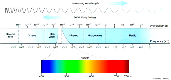
Which of the following is the infrared wavelength:
Solution
CONCEPT:
Electromagnetic waves or EM waves:
- The waves that are formed as a result of vibrations between an electric field and a magnetic field and they are perpendicular to each other and to the direction of the wave is called an electromagnetic wave.
- The accelerating charged particle produces an electromagnetic (EM) wave.
- A charged particle oscillating about an equilibrium position is an accelerating charged particle.
- Electromagnetic waves do not require any matter to propagate from one place to another as it consists of photons. They can move in a vacuum.
Infrared radiation:
- Infrared radiation (IR), sometimes known as infrared light, is electromagnetic radiation (EMR) with wavelengths longer than visible light.
- It is undetectable by the human eye.
- The range of the wavelength of the infrared spectrum is 25 μm – 750 nm.
- Most of the thermal radiation emitted by objects near room temperature is infrared.
- Infrared radiations are also referred to as heat or thermal waves.
EXPLANATION:
- The range of the wavelength of the infrared spectrum is 25 μm – 750 nm.
⇒ 10-4 cm = 10-6 m
⇒ 10-4 cm = 1 μm
- Hence, option 1 is correct.
-
Question 36
5 / -1
Which of the following is/are true?
Solution
The correct answer is option 4) i.e. All of the above
CONCEPT:
- Lorentz force: A charged particle moving relative to a magnetic field experiences a force due to the magnetic field. This force is called the Lorentz force.
- When a charged particle q is moving with a velocity of v in a magnetic field of intensity B, the Lorentz force (F) is given by:
\( \vec{F} = q(\vec{v}× \vec{B})\)
- Torque on a current loop: A current-carrying loop placed in a magnetic field will experience multiple magnetic forces on it due to the change in direction of current along the loop. Any two such equal and opposite force forms a couple and causes torque in the loop.
- The torque experienced by a current-carrying loop placed in a magnetic field is the vector product of the magnetic moment and the magnetic field.
It is given by:
Torque, τ = m × B
Where m is the magnetic moment and B is the magnetic field intensity.
- The magnetic moment is the product of the current flowing in the loop and the area of the loop. It is given by
Magnetic moment, m = IA
Where I is the current and A is the area.
EXPLANATION:
- From the equation of Lorentz force, any charged particle moving in a magnetic field experiences a force.
- When a current-carrying wire is placed in a magnetic field, the flow of charges causing the current in the wire is moving and therefore, experiences a force.
- A current loop in a magnetic field experiences a torque due to the couple acting on the loop.
Hence, all the given statements are correct.
-
Question 37
5 / -1
Which of the following statement is correct, when the length of a wire is increased by keeping the cross-sectional area constant.
Solution
CONCEPT:
- Resistivity (ρ): The property of a conductor that opposes the flow of electric current through them and is independent of the shape and size of the materials but depends on the nature and temperature of the materials is called resistivity.
- The unit for resistivity is the ohm-meter (Ω-m).
- The resistivity of a material depends on its nature and the temperature of the conductor.
- The resistivity of a material doesn't depend on its shape and size (length and area).
- Resistance: The property of any conductor that opposes the flow of electric current through it and depends on the shape and size of the materials, temperature, and nature of the materials is called resistance.
- It is denoted by R and the SI unit is the ohm (Ω).
- The resistance is given by:
\(⇒ R=\frac{ρ l}{A}\)
Where ρ = specific resistance, l = length of the wire, and A = cross-sectional area of the wire
CALCULATION:
- Specific resistance is a material property so it does not depend on the length, area, size, and shape of the wire.
- So when the length of a wire is increased by keeping the cross-sectional area constant its specific resistance will remain the same.
- The resistance of a wire is given as,
\(⇒ R=\frac{ρ l}{A}\) -----(1)
Where ρ = specific resistance, l = length of the wire, and A = cross-sectional area of the wire
- If the cross-sectional area of the wire is constant then,
⇒ R ∝ l -----(2)
- By equation 2 it is clear that the resistance of a wire is proportional to the length of the wire.
- Therefore if the length of a wire is increased by keeping the cross-sectional area constant then the resistance of the wire will also increase. Hence, option 3 is correct.
-
Question 38
5 / -1
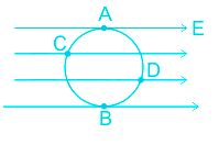
A uniform electric field in the plane of the paper as shown. Here A, B, C, D are the points on the circle V1, V2, V3, V4 are the potential at those points respectively. Then
Solution
CONCEPT:
- Electric lines of forces constitute the electric field and vice versa.
- Electric lines of force: Inside the electric field, The path along which a unit positive charge will move if it is free to do so is called electric lines of force.
- The tangent at any point to these lines gives the direction of the electric field at that point.
- E lectric lines of force always flow from higher potential to lower potential.
EXPLANATION:
- Electric lines of forces constitute the electric field and vice versa.
- Electric lines of force always flow from higher potential to lower potential.
- So in the given figure in the question, if we move from the left side to the right side, the potential will decrease.
so VC > VA = VB > VD
- Since line joining A and B points is perpendicular to electric lines of force so both points will be at the same potential.
- From the above observation; \({V_C} > {V_A},\;{V_B} > {V_D}\) is correct. So the correct answer is option 3.
-
Question 39
5 / -1
The relationship between conductivity σ and resistivity ρ of a material is
Solution
The correct answer is option 2) i.e. σ = ρ-1
CONCEPT:
- The resistivity of a material is defined as the resistance offered by a material of unit cross-sectional area and unit length.
It is represented as:
\(\Rightarrow ρ = \frac{RA}{l}\)
Where R is the resistance, l is the length of the material and A is the area of cross-section.
- Resistivity is an intrinsic property i.e. it is the same for a given type of material.
- Conductivity (σ) is the reciprocal of electrical resistivity.
EXPLANATION:
Since conductivity is the reciprocal of resistivity, \(σ = \frac{1}{\rho} = \rho^{-1}\)
-
Question 40
5 / -1
If the the amplitude of the modulating signal is greater than the amplitude of the carrier wave, then what will happen with the modulated signal?
Solution
CONCEPT:
Amplitude modulation:
- In amplitude modulation, the amplitude of the carrier is varied in accordance with the information signal.
- Here we explain the amplitude modulation process using a sinusoidal signal as the modulating signal.
- Let c(t) = Acsin(ωct) represent carrier wave and m(t) = Amsin(ωmt) represent the message or the modulating signal.
- So the modulated signal can be represented as,
⇒ cm(t) = [Ac + Am.sin(ωmt)].sin(ωct)
⇒ cm(t) = [Ac + μAc.sin(ωmt)].sin(ωct)
Where Ac = amplitude of the carrier wave, Am = amplitude of the modulating signal, ωc = angular frequency of the carrier wave, ωm = angular frequency of the modulating signal, and μ = modulation index
- The modulation index is given as,
\(\Rightarrowμ=\frac{A_m}{A_c}\)
- In practice, μ is kept \(≤q 1\) to avoid distortion.
- Using the trignomatric relation 2sinA.sinB = cos(A - B) - cos(A + B), we can represent the modulated signal as,
\(\Rightarrow c_m(t)=A_csin(ω_ct)+\frac{μ A_c}{2}cos(ω_c-ω_m)t-\frac{μ A_c}{2}cos(ω_c+ω_m)t\)
- Here (ωc - ωm) and (ωc + ωm) are respectively called the lower side and upper side frequencies.
- The modulated signal now consists of the carrier wave of frequency ωc plus two sinusoidal waves each with a frequency slightly different from ωc, known as sidebands.
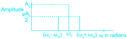
- As long as the broadcast frequencies (carrier waves) are sufficiently spaced out so that sidebands do not overlap, different stations can operate without interfering with each other.
EXPLANATION:
- We know that if c(t) = Acsin(ωct) represent carrier wave and m(t) = Amsin(ωmt) represent message signal, then the modulation index is equal to the,
\(\Rightarrowμ=\frac{A_m}{A_c}\)
- In practice, μ is kept ≤ q1 to avoid distortion.
If Am > Ac
Then μ > 1
- Hence, option 3 is correct.
-
Question 41
5 / -1
Two coherent sources of intensity ratio 25 ∶ 9 are used in an interference experiment. The ratio of intensities of maxima and minima in the interference pattern is:
Solution
Concept:
The intensity of the light ∝ width of the slit (W)
\(\frac{{{W_1}}}{{{W_2}}} = \frac{{{I_1}}}{{{I_2}}}\)
Intensity ∝ square of the amplitude
\(\frac{{{W_1}}}{{{W_2}}} = \frac{{{I_1}}}{{{I_2}}} = \frac{{a_1^2}}{{a_2^2}}\)
\( \frac{{{I_{max}}}}{{{I_{min}}}} = \frac{{{{\left( {{a_1} + {a_2}} \right)}^2}}}{{{{\left( {{a_1} - {a_2}} \right)}^2}}} \)
Calculation:
Given that, I1 = 25, I2 = 9
\(\frac{{{I_1}}}{{{I_2}}} = \frac{{25}}{9}\)
\(\begin{array}{l} \frac{{{I_1}}}{{{I_2}}} = \frac{{a_1^2}}{{a_2^2}} = \frac{{25}}{9}\Rightarrow \frac{{{a_1}}}{{{a_2}}} = \frac{5}{3} \end{array}\)
\(\begin{array}{l} \frac{{{I_{max}}}}{{{I_{min}}}} = \frac{{{{\left( {{a_1} + {a_2}} \right)}^2}}}{{{{\left( {{a_1} - {a_2}} \right)}^2}}} = \frac{{{{\left( {\frac{{{a_1}}}{{{a_2}}} + 1} \right)}^2}}}{{{{\left( {\frac{{{a_1}}}{{{a_2}}} - 1} \right)}^2}}} = \frac{{{{\left( {\frac{5}{3} + 1} \right)}^2}}}{{{{\left( {\frac{5}{3} - 1} \right)}^2}}} = {\left( {\frac{8}{2}} \right)^2} = \frac{64}{4} \end{array}\)
-
Question 42
5 / -1
In a PNP transistor working as a common-base amplifier, current gain is 0.92 and emitter current is 6 mA. The base current is
Solution
Concept:
Current gain (α):
It is defined as the ratio of change in collector current (Ic) to the corresponding change in emiiter current (Ie) at constant collector base voltage.
∴ Current gain \(\alpha = \frac{{{I_c}}}{{{I_e}}} \)
According to Kirchhoff's law -
Ie = Ib + Ic
Explanation:
Given - Current gain = 0.92 and Ie = 6mA
\(\alpha = \frac{{{I_c}}}{{{I_e}}} \)
∴ Ic = α × Ie
IC = 0.92 × 6 = 5.52 mA
Base current,
\({I_b} = {I_e} - {I_c} \Rightarrow {I_b} = 6 - 5.52 = 0.48\;mA\)
-
Question 43
5 / -1
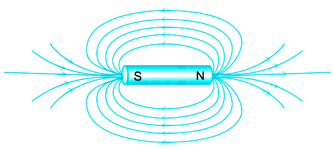
Magnetism at the center of a bar magnet is ______?
Solution
CONCEPT:
- Phenomena of Magnetism: The force of attraction and repulsion exhibited due to magnetic forces on magnetic materials and charged particles and related phenomena are known as magnetism.
- Bar Magnet: A bar magnet is a rectangular piece of an object, made up of ferromagnetic substances that show permanent magnetic properties.
- Field Lines: Magnetic field lines represent the strength and direction of the magnetic field at a particular point.
- The density of field lines represents the strength of the magnetic field.
- The more the density, the more is the strength.
EXPLANATION:
- The magnetic field at the center of a bar magnet is zero in ideal case.
- The field lines near the center is parallel to the bar magnet.
- The density of the field lines is maximum at the poles of the bar magnet and zero at the center which means that the magnitude of the magnetic field is small at the center.
- So, zero is the correct answer.
Additional Information
Though zero is correct for ideal case, practically it may not be zero.
-
Question 44
5 / -1
Unpolarized light in air falls on water surface (refractive index = 1.33) and achieves maximum polarization. The angle of incidence is
Solution
CONCEPT:
- The angle of incidence at which a beam of unpolarized light falling on a transparent surface is reflected as a beam of completely plane polarised light is called polarising or Brewster angle. It is denoted by ip.
- Brewster's law: It states that when a ray is passed through some transparent medium having refractive index μ at any particular angle of incidence, the reflected ray is completely polarized; and the angle between reflected and refracted ray is 900.
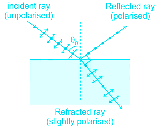
⇒ μ = tan θB
Where μ = refractive index and θB is Brewster's angle or polarizing angle (ip).
EXPLANATION:
Brewster's law:
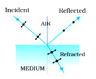
- The maximum polarization of a ray of light may be achieved by letting the ray fall on a surface of a transparent medium in such a way that the refracted ray makes an angle of 90° with the reflected ray.
\(⇒ tanθ _b=\frac {n_2}{n_1}\)
where θb is the angle of incidence, also called the Brewster angle, n2 is the refractive index of the second medium, and n1 is the refractive index of the first medium.
\(⇒ tanθ _b=\frac {1.33}{1}=1.33\)
- By method of elimination, since tan(45o) = 1, and tangent is an increasing function, the only option 4 is greater than 45 degrees. Therefore option 4 is correct.

- Equation of a transverse wave is given by;
\(⇒ y=Asin(kx-ω t)\)
where A is the amplitude, k the wavenumber, and ω the angular frequency.
Polarization:
- The wave is in the x-y plane, thus it is called a plane-polarized wave.
- The wavefield displaces in the y-direction, thus it is called y-polarized or linearly polarised wave.
- When two orthogonal electric field component vectors are of equal magnitude and are out of phase by exactly 90°, the wave is called circular polarized.
Polaroid:
- A polaroid consists of long-chain molecules aligned in a particular direction.
- The electric vectors along the direction of the aligned molecules get absorbed.
- When an unpolarized light wave is an incident on a polaroid then the light wave gets linearly polarized.
- This direction of the electric field vector is known as the pass-axis of the polaroid.
- The intensity of unpolarized light is generally reduced to 50% of the original when passed through a single polaroid.
Combination of polaroids:
- If unpolarized light is passed through two polaroids are placed at an angle θ to each other, the intensity of the polarized wave is
\(⇒ I = I_0cos^2θ\)
where I is the intensity of the polarized wave, I0 is the intensity of the unpolarized wave.
-
Question 45
5 / -1
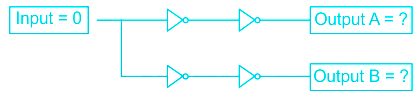
In the below circuit the outputs are
Solution
CONCEPT
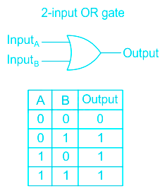
Logic gates: It is an electric circuit, which works on simple Boolean algebra to perform logical operation for one or more binary inputs that produces single binary output.
Types of Logic gates:
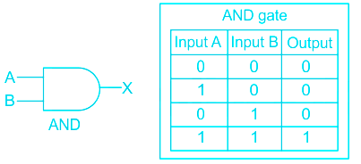
AND Gate: If both the inputs are high, it produces a high output.
The Boolean algebra for AND gate is X = A. B
OR gate: If any of the input is high, it produces a high output.
The Boolean algebra for OR gate is X = A + B
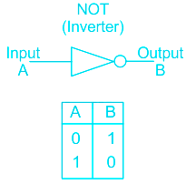
NOT gate: It inverts the input. Whatever the input is given, it changes its value at output.
- The Boolean algebra for NOT gate is X = X̅
EXPLANATION
Since NOT gate is inverter it inverts input so,
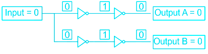
This is the flow process of each signal.
⇒
Option 1 is correct.
-
Question 46
5 / -1
A proton is moving at a speed of 5.0 × 10⁴ m/s. The de Broglie wavelength associated with it is _____.
(mp = 1.67 × 10⁻²⁷ kg, h = 6.63 × 10⁻³⁴ J s)
Solution
Concept:
De Broglie wavelength: All particles could be treated as matter waves with a wavelength.
Frequency is given by the following equation:
\(λ = \frac{h}{mv}\)
Where λ is de Broglie wavelength, h is Planck's const, m is mass, v is the velocity.
When an electron is accelerated its de Broglie wavelength is given by
\(λ = \frac{\sqrt{150}}{\sqrt V} A\)
Where V is the potential difference in which electron is accelerated.
Calculation:
Given that, v = 5 × 10⁴, mp = 1.67 × 10⁻²⁷ kg, h = 6.63 × 10⁻³⁴ J s
Frequency is given by,
\(λ = \frac{h}{mv}\) = \(\frac{6.63×10^{-34}}{1.67× 10^{-27}×5×10^{4}}=0.79×10^{-11}\)
The de Broglie wavelength associated with it is 0.79 × 10⁻¹¹m.
-
Question 47
5 / -1
Which type of behaviour is shown by a pure Germanium at absolute zero temperature?
Solution
CONCEPT:
- The material which is not a good conductor or a good insulator is called a semiconductor.
- For example: Silicon, Germanium, etc.
- The charge carriers which are present in more quantity in a semiconductor compared to other particles are called the majority charge carrier.
- The impurity atoms added are called dopants and semiconductors doped with the impurity atoms are called extrinsic or doped semiconductors.
- The pure form of semiconductor is called an intrinsic semiconductor.
Intrinsic Semiconductors:
- A pure semiconductor is called an intrinsic semiconductor. It has thermally generated current carriers.
- They have four electrons in the outermost orbit of the atom and atoms are held together by a covalent bond.
- Fermi energy level lies at the center of the conduction band (C.B) and valence band (V.B) in an intrinsic semiconductor.
- Because of fewer charge carriers at room temperature, intrinsic semiconductors have low conductivity so they have no practical use.
EXPLANATION
- An ideal, perfectly pure semiconductor (with no impurities) is called an intrinsic semiconductor.
- At absolute zero temperature valence band is full of electrons and the conduction band is empty, hence there are no free electrons in the conduction band and holes in the valence band.
- The charge carrier concentration is zero. Hence intrinsic semiconductor behaves like an insulator
- Hence, at zero temperature the intrinsic semiconductor behaves like an insulator. The correct option is 3.
-
Question 48
5 / -1
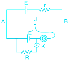
In the potentiometer arrangement, a cell has a balancing point at 30 cm length of wire whose emf is 1.5V. If the cell is replaced by another cell, the balancing point shifts to 60 cm. What is the emf of the replaced cell?
Solution
CONCEPT:
POTENTIOMETER:
- A potentiometer is a device mainly used to measure the emf of a given cell and to compare the emf of cells.
- It is also used to measure the internal resistance of a given cell.
- If Potential across AJ (V) is equal to emf E’ then no current will flow in the galvanometer circuit this condition to known as null deflection position, length AJ (x) is known as balancing length.
Potential gradient (k) :
- The potential difference (or fall in potential) per unit length of wire is called potential gradient i.e.
\(\Rightarrow k =\frac{V}{l}\)
Where V = Potential difference and l = length of the wire
EXPLANATION:
- A potentiometer is used to compare the emfs of two cells.
Given, emf of first cell E1 = 1.5V
Balancing point l1 = 30 cm
Balancing point l2 = 60 cm
⇒ E1/E2 = l1/l2
⇒ 1.5/E2 = 30/60
⇒ E2 = 1.5 × 2
⇒ E
2 = 3V
-
Question 49
5 / -1
Light of wavelength 600 nm is incident normally on the slit of width 2 mm. What will be the angular width of central maxima at a distance of 1 m from the slit?
Solution
CONCEPT:
- When the monochromatic light ray falls on a single slit then it gets diffracted from the slit and form a bright and dark pattern on the screen.
- The bright pattern is also called maxima and the dark pattern is called minima.
- At maxima the intensity is maximum and at minima the intensity of light is minimum.
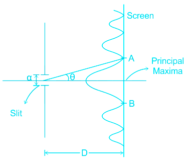
- Here AB is the width of the central maxima/principal maxima and 2θ will be the angular width of principal maxima.
- \(\sin \theta =\frac{n\lambda }{a}\)
Where λ = wavelength of the light, n = an integer value, a = slit width, and D = distance of the screen from the slit.
Here θ is very small.
CALCULATION:
Given - λ = 600 nm = 600 × 10-9 m, D = 1 m and a = 2 mm = 2 × 10⁻³ m
The angular width of the central maxima (2θ) is
\({\rm{Angular\;width\;}}\left( {2\theta } \right) = \frac{{2n\lambda }}{a}\)
For principal maxima, n = 1
\(\Rightarrow {\rm{Angular\;width\;}}\left( {2\theta } \right) = \frac{{2 \times 600 \times {{10}^{ - 9}}}}{{2 \times {{10}^{ - 3}}{\rm{\;}}}} = 6 \times {10^{ - 4}}rad\)
As rad = 180/π
\(\Rightarrow {\rm{Angular\;width\;}}\left( {2\theta } \right) = 6 \times {10^{ - 4}} \times \frac{{180}}{\pi } = 0.034^\circ\)
-
Question 50
5 / -1
In a Van de Graaff generator, when a metallic wire is connected between the two conductors, the charge flows from
Solution
CONCEPT:
Van de Graaff generator
Principle:
- Static charges are accumulated on a large radius conducting shell using corona discharge.
Application
- This is a machine that can build up high voltages of the order of a few million volts.
- The resulting large electric fields are used to accelerate charged particles (electrons, protons, ions) to high energies needed for experiments to probe the small-scale structure of matter.
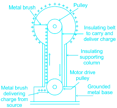
Working
- Charges from a ground metal base are collected by an insulating belt.
- These charges are driven upward by the belt attached to the pulley
- The charges are collected on a small conducting sphere attached to the pulley with the help of a metal brush.
- A metallic wire is then connected between the small and the large conducting spheres.
- The charge transfers to the large sphere due to its low potential.
- The process is repeated to accumulate a high amount of static charge on the large sphere.
EXPLANATION:
- The potential at the smaller sphere is less than the potential at the larger sphere.
- This potential difference is independent of the charge at the larger sphere.
- Therefore any charge on the smaller sphere flows to the larger sphere. Therefore option 3 is correct
Additional Information
Mathematics
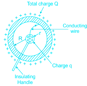
- We have a large spherical conducting shell of radius R, on which we place a charge Q.
- This charge spreads itself uniformly all over the sphere.
- The field outside the sphere is just that of a point charge Q at the center.
- The field inside the sphere is zero.
- The potential outside is that of a point charge.
- The potential inside is constant and has a value same as the value at the radius R.
- Potential inside conducting spherical shell of radius R carrying charge Q
\(\Rightarrow V = \frac {KQ}{R}\)
- A small sphere of radius r, carrying some charge q, is placed into the large one, at the center.
- The potential due to this new charge q is
\(\Rightarrow V = \frac {Kq}{r}\) at the surface of the small sphere
\(\Rightarrow V = \frac {Kq}{R}\) at the surface of the large sphere
- The net potential at a distance R from the center due to both the spheres is
\(\Rightarrow V(R) = \frac {KQ}{R}+\frac {Kq}{R} \)
- The net potential at a distance r from the center due to both the spheres is
\(\Rightarrow V(r) = \frac {KQ}{R}+\frac {Kq}{r} \)
- The potential difference between points at distance r and R from the center is
\(\Rightarrow V(r)-V(R) = \frac {KQ}{R}+\frac {Kq}{r} - \frac {KQ}{R}-\frac {Kq}{R} =Kq(\frac {1}{r}-\frac {1}{R})\)
- Thus potential at the smaller sphere surface is higher than the potential at the larger sphere surface.
- Therefore all the charge at the smaller sphere gets transferred to the larger sphere.


 ×
×

 Sign in
 Profile
 Signout


