Self Studies

Structural Analysis Test 1

Result Self Studies

Structural Analysis Test 1
  • Score

    -

    out of -
  • Rank

    -

    out of -
TIME Taken - -
Self Studies

SHARING IS CARING

If our Website helped you a little, then kindly spread our voice using Social Networks. Spread our word to your readers, friends, teachers, students & all those close ones who deserve to know what you know now.

Self Studies Self Studies
Weekly Quiz Competition
  • Question 1
    2 / -0.33

    In the virtual work method of plastic analysis of steel structure, the virtual quantity is

    Solution

    In the virtual work method of plastic analysis of steel structure, the virtual quantity is displacement.

    Virtual work arises in the application of the principle of least action to the study of forces and movement of a mechanical system. The work of a force acting on a particle as it moves along a displacement will be different for different displacements. Among all the possible displacements that a particle may follow, called virtual displacements, one will minimize the action. This displacement is therefore the displacement followed by the particle according to the principle of least action. The work of a force on a particle along a virtual displacement is known as the virtual work.

    Principle of virtual work: (unit-load Method)

    Developed by Bernoulli:

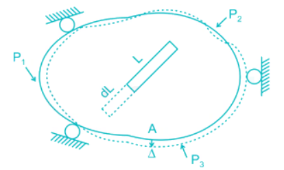
    To find Δ at point A du to loads P1, P2, P3. Remove all loads, apply virtual load P’ on point A.

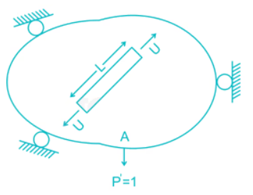
    For simplicity P’ = 1

    It creates internal load u on representative element.

    Now remove this load, apply P1, P2, P3 due to which pt. A will be displaced by Δ

    ∴ External virtual work = 1.Δ

    Internal virtual work = u.dL

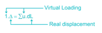
    P' = 1 = external virtual unit load in direction of Δ.

    u = internal virtual load acting on element in direction of a dL.

    Δ = external displacement caused by real loads.

    dL = internal deformation caused by real loads.

  • Question 2
    2 / -0.33

    The figure below shows the displacement caused by load P at two points 1 and 2 respectively. According to Maxwell reciprocal theorem which option is CORRECT.

    Solution

    The Maxwell reciprocal theorem, states that the deflection at a point A in the direction of  1 due to load at point B in the direction of 2 is equal in the magnitude to the deflection of point B in the direction of 2 produced by a load applied at A in direction 1.

    Hence,

    δ12 = δ21

  • Question 3
    2 / -0.33

    A fixed beam AB is subjected to a triangular load varying from zero at end A to ‘w’ per unit length at end B. The ratio of fixed end moment at B to A will be

    Solution

  • Question 4
    2 / -0.33

    Find the carry over moment at support B, in the beam shown with internal hinges at C & D:-

    Solution

    The beam has internal hinges at C & D, so the beam can be break down as shown

    In AC section moment applied = M

    So the reaction will be = M/L/2 = 2/ML

    The carry – over moment at B = 2M/L × L/4 = M/2

  • Question 5
    2 / -0.33
    Pick the incorrect statement among the following regarding Influence line diagram (ILD):
    Solution

    An influence line represents the variation of either the reaction, shear, moment, or deflection at a specific point in a member as a concentrated force moves over the member.

    Advantages of drawing ILD are as follows:

    i) To determine the value of quantity (shear force, bending moment, deflection, etc.) for a given system of loads on the span of structure.

    ii) To determine the position of a live load for the quantity to have the maximum value and hence to compute the maximum value of the quantity.

    ILD can be drawn for statically determinate as well as indeterminate structures. ILD for statically determinate and indeterminate structures are linear and nonlinear respectively.

    Infinite numbers of ILD can be drawn for a particular structural member for computing different quantity at different sections.
  • Question 6
    2 / -0.33
    Which of the following is not true regarding assumptions made for matrix method of structural analysis?
    Solution

    Flexibility matrix method and stiffness matrix method are two matrix methods.

    Following are the assumptions made for matrix analysis of the structure:

    a) Material of all the structural member obeys Hooke’s law.

    b) Members are subjected to small deflections.

    c) Change in length under a deflection perpendicular to member length is 0.

    d) Principal of superposition is applicable.

    e) Frames – members are considered to be inextensible.
  • Question 7
    2 / -0.33

    The correct order of strain energy in the beams:-

    Solution

    Deflection, δ = ∂U/∂F

    In which beam deflection is higher, strain energy stored will be maximum.

    In cantilever, the deflection will be highest.

    The deflection of a simply supported beam is higher than propped cantilever as one of the support is fixed.

    In a fixed beam, the deflection will be minimum.

    So,

    δcantilever >  δsimple-support > δpropped cantilever > δfixed

    ∴ Ufixed < Uproped-cantilever < Usimple-support < Ucantliver

  • Question 8
    2 / -0.33

    The ratio of the deflections of the free end of a cantilever due to an isolated load at 1/3rd and 2/3rd of the span is

    Solution

    Ist condition:

    For a cantilever beam subjected to load W at distance of L/3 from free end, the deflection is given by:

    \({\rm{y}}{{\rm{c}}_1} = \frac{{\rm{W}}}{{3{\rm{EI}}}} \times {\left( {\frac{{2{\rm{L}}}}{3}} \right)^3} + \frac{{\rm{W}}}{{2{\rm{EI}}}}{\left( {\frac{{2{\rm{L}}}}{3}} \right)^2} \times \frac{{\rm{L}}}{3} = {\frac{{28{\rm{WL}}}}{{162{\rm{EI}}}}^3}\)

    IInd condition:

    For a cantilever beam subjected to load W at distance of 2L/3 from free end:

    \({\rm{y}}{{\rm{c}}_2} = \frac{{\rm{W}}}{{3{\rm{EI}}}} \times {\left( {\frac{{\rm{L}}}{3}} \right)^3} + \frac{{\rm{W}}}{{2{\rm{EI}}}}{\left( {\frac{{\rm{L}}}{3}} \right)^2} \times \frac{{2{\rm{L}}}}{3} = \frac{{8{\rm{W}}{{\rm{L}}^3}}}{{162{\rm{EI}}}}\)

    \({\rm{Ratio\;}}\left( {\rm{r}} \right) = \frac{{{\rm{y}}{{\rm{c}}_1}}}{{{\rm{y}}{{\rm{c}}_2}}} = \frac{{{{\frac{{28{\rm{WL}}}}{{162{\rm{EI}}}}}^3}}}{{\frac{{8{\rm{W}}{{\rm{L}}^3}}}{{162{\rm{EI}}}}}} = \frac{{28}}{8} = \frac{7}{2}\)

    \(\therefore \frac{{{\rm{y}}{{\rm{c}}_2}}}{{{\rm{y}}{{\rm{c}}_1}}} = \frac{2}{7}\)

  • Question 9
    2 / -0.33

    The strain energy stored (U) in the cantilever beam shown is –

    Solution

  • Question 10
    2 / -0.33
    The flexibility matrix for a beam is given as \(\left| {\begin{array}{*{20}{c}} b&a\\ d&c \end{array}} \right|,\) which of the following represent the correct relation between b and c, given that b and c are non-zero real numbers.
    Solution

    Concept:

    The flexibility matrix has the following two main properties:

    1. The flexibility matrix is square symmetric matrix due to Maxwell’s reciprocal theorem which me Ans: that its diagonal elements are always equal.

    2. The diagonal elements of flexibility matrix are always positive due to Castigilanostheorem–II.

    Calculation:

    a = d (using 1st property)

    b > 0 and c > 0 (using 2nd property)

    ∴ b = c, b > 0, c > 0

  • Question 11
    2 / -0.33

    Find the vertical displacement of joint B if the spring constant k = 1 KN/mm and the rigid beam is loaded as shown below:-

    Solution

  • Question 12
    2 / -0.33

    The members carrying zero force (i.e. zero-force members) in the truss shown in the figure, for any lad P > 0 with no appreciable deformation of the truss (i.e. with no appreciable change in angles between the members), are

    Solution

    If at a joint 3 members meet out of which 2 are collinear then force in 3rd member will be zero provided there is no load/reaction at that joint.

    ∴ FGC = 0, FFB = 0 and FHD = 0

    i.e. forces in the member GC, FB, HD is equal to zero

    Now, considering joint E:

    ∵ FEH = RE

    There is no horizontal force.

    ∴ FDE = 0

    Also considering joint D, we can say that force in member CD = 0

  • Question 13
    2 / -0.33

    Find the rotation of joint B if the frame is loaded as shown below:

    Solution

  • Question 14
    2 / -0.33

    All members of the frame shown below have equal flexural rigidity EI. Calculate the rotation of joint O if moment M is applied?

    Solution

    Concept :-

    Stiffness value, K when far end is fixed = 4EI/L

    Stiffness value, K when far end is roller = 3EI/L

    Stiffness value, K when far end is guided roller = EI/L

    For stiffness coefficient when far end is guided roller support refer :-

    Advanced Structural Analysis, Prof. Devdas MenonDepartment of Civil Engineering, Indian Institute of Technology, Madras

    Module - 5.3 ,Lecture - 29Matrix Analysis of Beams and GridsPage No. - 9

  • Question 15
    2 / -0.33

    Determine the kinematic indeterminacy of the beam shown below:

    Solution

    Dk = 3J – re + rr

    J = No. of joints

    re = External support Reactions

    rr = Released Reactions

    re = 7

    J = 6

    rr = m – 1

    m = No. of members meeting at internal hinge

    At B:

    rr = 2 – 1 = 1

    At D:

    rr = 2 – 1 = 1

    Therefore,

    Dk = 3 × 6 – 7 + 2

    Dk = 13

  • Question 16
    2 / -0.33

    The total degree of indeterminacy (external + internal) for the bridge truss is :

    Solution

    Dsi = m – (2j – 3)

    m = 20

    j = 10

    Dsi = 20 – (2 × 10 – 3) = 3

    Dse = re – 3 = 4 – 3 = 1

    Total indeterminacy = 3 + 1 = 4

  • Question 17
    2 / -0.33

    A two hinged semi-circular arch of radius R carries a concentrated load W at the crown. The horizontal thrust is

    Solution

  • Question 18
    2 / -0.33

    A three – hinged parabolic arch rid of span L and crown rise ‘h’ carries a uniformly distributed superimposed load of intensity ‘w’ per unit length. The hinges are located on two abutments at the same level and the third hinge at a quarter span location from the left-hand abutment. The horizontal trust on the abutment is:

    Solution

  • Question 19
    2 / -0.33

    In a two-hinged parabolic arch (consider arch to be initially unloaded) an increase in temperature induces -

    Solution

    As loading is UDL and the shape of the arch is parabolic so there will be no moment in the arch rib.

    But as the temperature increases in a two hinged arch (degree of indeterminacy one), the horizontal thrust will increase.

    Moment due to horizontal thrust is – Py.

    So maximum bending moment will be at crown as crown has highest value of y. 

  • Question 20
    2 / -0.33

    While fabricating a square truss, the member BD was somehow defectively short (fabrication defect) as shown in the figure. So stress developed in the member AC immediately after constructing the truss by force would be

    Solution

  • Question 21
    2 / -0.33
    For a linear elastic frame, if the stiffness matrix is doubled with respect to the existing stiffness matrix, the deflection of the resulting frame will be
    Solution

    Stiffness (k) is defined as the force per unit deflection.

    K = P/δ 

    ⇒ δ = P/K

    If stiffness matrix is doubled

    i.e. K’ = 2K

    then,

    δ = P/K'

    δ = P/2K

    δ = (1/2)P/K

    δ’ = δ/2.  

    Therefore, if the stiffness matrix is doubled with respect to the existing stiffness matrix, the deflection of the resulting frame will be half the existing value.

  • Question 22
    2 / -0.33

    The forces in members BE, CD, BC in the truss shown

    Solution

  • Question 23
    2 / -0.33

    Stiffness coefficient k23 for the beam shown below is

    Solution

    For k33 Apply unit displacement along 3 and restraining the displacement in 2 and 1

  • Question 24
    2 / -0.33

    Length of each member of the truss shown in the figure is 3m. Member AB and CD are subjected to a temperature rise of 40°C and coefficient of thermal expansion, α is 12 × 10-6/°C. The vertical deflection at joint E is________

    Solution

    To find the vertical deflection at joint E, a unit vertical load is applied at joint E and the forces in member AB and CD are to be found out.

    FAB sin 60° = 0.5  

    FAB = 0.577 (compressive)

    Similarly, FCD = 0.577 (compressive)

    due to increase in temperature, the increase in length of AB & CD = L ∝ t

    = 3 × 12 × 10-6 × 40

    = 0.00144 m

    So the deflection of joint E,

    δ = Σ kδ’

    where, k = Force produced in each member when a unit downward load is applied at joint E.

               δ’ = Deflection produced in the concerned member (AB & CD)  due to temparature rise.

    = (- 0.577) × (0.00144) + (- 0.577) × (0.00144)

    = - 0.00166 m

    = 1.66 mm (upward)

    [‘–’ means our assumed downward deflection is wrong, it will deflect upward]

  • Question 25
    2 / -0.33

    Uniformly distributed load w per unit length is suspended from a cable between point A and B. If the points A and B are at the same level at distance 'l' and central sage of the cable is h, the horizontal thrust developed of supports is -

    Solution

Self Studies
User
Question Analysis
  • Correct -

  • Wrong -

  • Skipped -

My Perfomance
  • Score

    -

    out of -
  • Rank

    -

    out of -
Re-Attempt Weekly Quiz Competition
Self Studies Get latest Exam Updates
& Study Material Alerts!
No, Thanks
Self Studies
Click on Allow to receive notifications
Allow Notification
Self Studies
Self Studies Self Studies
To enable notifications follow this 2 steps:
  • First Click on Secure Icon Self Studies
  • Second click on the toggle icon
Allow Notification
Get latest Exam Updates & FREE Study Material Alerts!
Self Studies ×
Open Now