Concept:
According to Thevenin’s theorem, any linear circuit across a load can be replaced by an equivalent circuit consisting of a voltage source Vth in service with a resistor Rth as shown:
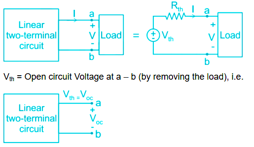
To evaluate the Thevenin Resistance, we consider the following two cases:
Case 1: Circuits with independent Sources only
If the network has no dependent sources, we turn off all independent sources. Rth is the input resistance of the network looking between terminals a and b.
Case 2: Circuit with Both Dependent and independent sources
We may use one of the two methods:
Using a Test Source:
We apply a voltage source V0 at terminals a and b and determine the resulting current I0.
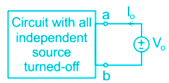
Then Rth = V0/I0
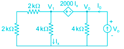
Application:
Since there are no independent sources present in the network, the Thevenin’s voltage will simply be zero i.e.
VTH = 0 V
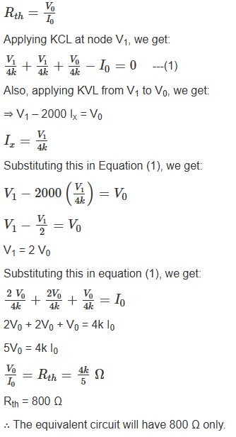
Now, because of the pressure of a dependent source, we will be a test charge to evaluate the Thevenin equivalent resistance, i.e.


 ×
×

 Sign in
 Profile
 Signout


