Self Studies

Network Theory Test 2

Result Self Studies

Network Theory Test 2
  • Score

    -

    out of -
  • Rank

    -

    out of -
TIME Taken - -
Self Studies

SHARING IS CARING

If our Website helped you a little, then kindly spread our voice using Social Networks. Spread our word to your readers, friends, teachers, students & all those close ones who deserve to know what you know now.

Self Studies Self Studies
Weekly Quiz Competition
  • Question 1
    2 / -0.33

    For the circuit shown in the figure, the steady-state response v0(t) is given by:

    Solution

    Transforming the circuit into s-domain, we get:


  • Question 2
    2 / -0.33

    Under steady-state condition, the energy stored in the circuit is:

    Solution

    At steady state, capacitor will be open-circuited so, equivalent circuit is;

    From figure,

  • Question 3
    2 / -0.33

    In the following circuit (Fig.) i(t) under steady state is

    Solution

    For DC voltage, the capacitor acts as an open circuit and the inductor act as a short circuit.

    Hence no current flows in the circuit.

    For AC supply, the impedance,

  • Question 4
    2 / -0.33

    In the given circuit, the AC source has ω = 100 rad / s. Considering the inductor and capacitor to be ideal, the correct choice (s) is (are)

    Solution

  • Question 5
    2 / -0.33

    Consider the voltage and current expressions across a load as given below

    v = -100 cos (314 t + 15°)

    i = 50 sin (314 t - 45°)

    Then the active power delivered to the load is:

    Solution

    Given that:

    v = -100 cos (314 t + 15°)

    Since cos θ = sin (90° - θ)

    - cos θ = sin (θ - 90°)

    The above voltage in terms of sin can be written as:

    v = -100 cos (314 t + 15°) = 100 sin (314 t + 15° - 90°)

    v = 100 sin (314 t - 75°)

    Also given:

    i = 50 sin (314 t - 45°)

    ∴ The voltage and current phasors can now be drawn as:

  • Question 6
    2 / -0.33

    What is the voltage across the capacitor at resonance?

    Solution


    The voltage across the inductor and the capacitor will be finite and of equal magnitude. Please note that the voltage across the LC combination is zero, as LC becomes a short circuit at resonance.

  • Question 7
    2 / -0.33

    Consider the circuit, consisting of an AC function generator V(t) = V0 sin 2πft with V0 = 5 V, an inductor L = 8 mH, resistor R = 5 Ω and a capacitor C = 100 μF. Which of the following statements are true if we vary the frequency?

    Solution

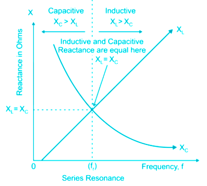
    The resonance curve of the series RLC circuit is given above

    • At below resonance frequency, XL is low and XC is high → circuit behaves like a capacitive circuit (leading power factor)
    • At the resonance frequency, XL equals to XC → circuit behaves like a purely resistive circuit (Unity power factor)
    • At the above resonance frequency, XL is high and XC is low → circuit behaves like an inductive circuit (lagging power factor)

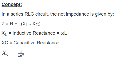
    At resonance, the magnitude of inductive reactance is equal to the magnitude of capacitive reactance.

    ∴ XL = XC

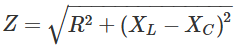
    At this condition, Z = R.

    Hence at resonance, the impedance is purely resistive and it is minimum.

    Current in the circuit, I = V/Z

    As impedance is minimum the current is maximum.

    As impedance is purely resistive, the power factor is unity.​

    Application:

    The current in the circuit would be maximum at the resonant frequency.

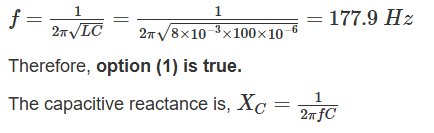
    The capacitive reactance is inversely proportional to the frequency and hence capacitive reactance decreases with frequency.

    Therefore, option (2) is false.

    At resonance, the circuit is purely resistive and hence the current in the circuit is in phase with the source voltage.

    Therefore, option (3) is false.

  • Question 8
    2 / -0.33

    The low-frequency circuit impedance and the high-frequency circuit impedance for a series resonant circuit respectively are

    Solution

    At ω = ω0, i.e. at the resonant frequency, the inductive reactance is equal to the capacitive reactance. At this condition, impedance is purely resistive, and it is equal to R. The impedance is maximum in this case.

    At ω = ∞, Z = infinity and the impedance is inductive.

  • Question 9
    2 / -0.33

    The following circuit (shown in Figure) resonates at

    Solution

    Concept:

    At resonance, the impedance of the circuit is purely resistive. To find the resonant frequency of the any given circuit, we need to equate the imaginary term of the impedance or admittance to zero.

    Calculation:

  • Question 10
    2 / -0.33

    The response of a series RLC circuit fed from a fixed rms voltage and variable frequency source is represented graphically in the given figure. Match List - I with List –II and select the correct answer using the codes gives below the lists:

    Solution

    In a series RLC circuit, the impedance is given by

    R is resistance

    L is inductive reactance = ωL

    XC is capacitive reactance = -1/ωC

    (XL – XC) is net reactance

    At the resonant frequency, inductive reactance is equal to capacitive reactance i.e. XL = XC

    So, at this condition the impedance is minimum, and it is equivalent to R.

    Therefore, BB represents the impedance waveform having a minimum value at the resonant frequency.

    As I = V/Z, the current is maximum at the resonant frequency.

    Therefore, AA represents the current waveform having a maximum value at the resonant frequency.

  • Question 11
    2 / -0.33

    Let the resonant frequency of the circuit A is ωA­ and the circuit B is ωB as shown in the figure.

    Which of the following statement is true?

    Solution


    The values of ωA and ωare different ωA is dependent on the value of R whereas ωis independent of the value of R.

  • Question 12
    2 / -0.33

    A parallel circuit has two branches. In one branch R and L are in series and in the other branch R and C are in series. The circuit will exhibit unity power factor when

    Solution

  • Question 13
    2 / -0.33

    For the circuit given below, R = 2.4 kΩ, C = 50 pF, and L = 2 μH. The smallest permissible value of the load resistor RL so that the quality factor of the circuit is not to drop below 7.5, is ______

    Solution


  • Question 14
    2 / -0.33

    Determine the resonant frequency (in mHz) for t > 0 of the network shown below

    Solution

  • Question 15
    2 / -0.33

    Consider the RLC network shown in the figure below.

    The resonant frequency (ω0) of the above network is given by

    Solution

    At resonance, the net impedance across the terminal will be purely resistive, i.e. imaginary part of the impedance will be zero.

    In phasor domain, the circuit is redrawn as:

  • Question 16
    2 / -0.33

    The response of the capacitor voltage in a series RC circuit is shown below:

    Which of the following represents the correct transient equation for the capacitor voltage?

    Solution

    Concept:

    The capacitor voltage in a series RC circuit is given by:

    v(t) = v(∞) + { v(0+) - v(∞) }e-t/τ

    where, v(0+) = Initial voltage across capacitor

    v(∞) = Steady state voltage across capacitor

    Calculation:

    Given, v(0+) = 2 V

    v(∞) = 10 V

    v(t) = 10 + { 2 - 10 }e-t/τ

    v(t) = 10 - 8e-t/τ

  • Question 17
    2 / -0.33

    In the circuit shown below, the initial capacitor voltage is 4V. Switch S1 is closed at t = 0. The charge (in μC) lost by the capacitor from t = 25 μs to t = 100 μs is ____________.

    Solution

    Concept:

    The transient equation for the voltage across a capacitor is given by,

    Time constant  = RC = 5 × 5 × 10 -6 = 25 × 10-6 secs

    Equation for the voltage across capacitor is given by:

     (as there is no active source in the network the capacitor dicharges and voltage acorss capacitor will be zero at time t = ∞)

  • Question 18
    2 / -0.33

    The time constant of the network shown in the figure below is

    Solution

  • Question 19
    2 / -0.33

    In the given circuit, find the current I in the 3-kΩ resistor at time t = 2 sec.

    Solution

    At time t = 2 sec

    First switch will be in the open condition because it closes at 5th second

    Second switch will be in a closed state because it gets opened at 3rd second.

    So circuit at t = 2 s reduces to

    ∴ i = 6 / 3000 A

    i = 2 mA

  • Question 20
    2 / -0.33

    Two inductors L1 (inductance 1mH, internal resistance 3Ω) and L2 (inductance 2mH, internal resistance 4Ω) and a resistance R (resistance = 12Ω) are connected in parallel across a 5V battery. The circuit is switched on at time t = 0, the ratio of maximum to minimum current (Imax/Imin) drawn from the battery is:

    Solution

    Concept:

    An inductor does not allow a sudden change in current, i.e.

    i(0-) = i(0+)

    Application:

    After switching the inductors will draw no current as the switch was initially open.

    At t = 0+, the current drawn from the battery will be:

    This current will be minimum because only 12 Ω resistance is acting.

    After steady-state ( t = ∞), both the inductors will be short-circuited and the equivalent resistance will be minimum (parallel combination).

    ∴ The current drawn from the battery will be maximum, i.e.

  • Question 21
    2 / -0.33

    In the circuit shown below, the current excitation is is(t) = 5 u(-t) A. The current iL(t) for t ≥ 0 is _____.

    Solution


  • Question 22
    2 / -0.33

    In the circuit shown below, a step input voltage of magnitude 5 V is applied at node A at time t = 0. If the capacitor has no charge for t < 0, the voltage at node P at t = 6 μs is ________ V. (Answer should be rounded off to two decimal places)

    Solution

  • Question 23
    2 / -0.33

    In the circuit shown below, find out the value of i(0+) and  If switch is closed at t = 0 -

    Solution

    Concept:

    At steady state for DC excitation inductor will be replaced by a short circuit and the capacitor will be replaced by an open circuit.

    An inductor does not allow sudden change of current .

    Hence, iL(0-) = iL(0+)

    A capacitor does not allow sudden change of voltage.

    Hence, VC(0-) = VC(0+)

    Voltage across inductor → VL = L diL/dt

    Calculation:

    Before operation of the switch at t = 0- 

     iL(0-) = 0 A

    VC(0-) = 0 V

    After closing the switch at t = 0+

     iL(0-) = iL(0+) = 0 A (zero current implies replace inductor with open circuit)

    VC(0-) = VC(0+) = 0 V (zero voltage implies replace capacitor with close circuit)

  • Question 24
    2 / -0.33

    In the circuit shown below, the switch S is closed at t = 0 and opened again at t = π sec. Prior to closing the switch at t = 0, Vc1 = 10 V while L and C2 do not have any stored energy. Find the voltages Vc1 and Vc2 at t = π sec. C1 and C2 = 1 F, L = 2 H

    Solution

    Concept:

    The transient equation is not applicable for the circuit with an order greater than 1. For such circuits, Laplace transform is used.

  • Question 25
    2 / -0.33

    For the circuit shown below v(t) = 10e-4t V and i(t) = 0.2e-4t A, then the time in (ms) taken by capacitor to dissipate 50% of its initial energy is:

    Solution


Self Studies
User
Question Analysis
  • Correct -

  • Wrong -

  • Skipped -

My Perfomance
  • Score

    -

    out of -
  • Rank

    -

    out of -
Re-Attempt Weekly Quiz Competition
Self Studies Get latest Exam Updates
& Study Material Alerts!
No, Thanks
Self Studies
Click on Allow to receive notifications
Allow Notification
Self Studies
Self Studies Self Studies
To enable notifications follow this 2 steps:
  • First Click on Secure Icon Self Studies
  • Second click on the toggle icon
Allow Notification
Get latest Exam Updates & FREE Study Material Alerts!
Self Studies ×
Open Now