Self Studies
Selfstudy
Selfstudy

Force and Torque on Current-Carrying Conductors Test - 1

Result Self Studies

Force and Torque on Current-Carrying Conductors Test - 1
  • Score

    -

    out of -
  • Rank

    -

    out of -
TIME Taken - -
Self Studies

SHARING IS CARING

If our Website helped you a little, then kindly spread our voice using Social Networks. Spread our word to your readers, friends, teachers, students & all those close ones who deserve to know what you know now.

Self Studies Self Studies
Weekly Quiz Competition
  • Question 1
    1 / -0.25
    A circular loop is placed in an external magnetic field. How is the torque 'τ' related to radius 'r' of the loop?
    Solution

    The correct answer is option 2) i.e. 

    CONCEPT:

    • Torque on a current loop: A current-carrying loop placed in a magnetic field will experience multiple magnetic forces on it due to the change in direction of current along the loop. Any two such equal and opposite force forms a couple and causes torque in the loop.
      • The torque experienced by a current-carrying loop placed in a magnetic field is the vector product of the magnetic moment and the magnetic field.

    It is given by:

    Torque, τ = m × B

    Where m is the magnetic moment and B is the magnetic field intensity.

    • The magnetic moment is the product of the current flowing in the loop and the area of the loop.

    It is given by:

    Magnetic moment, m = IA

    Where I is the current and A is the area.

    EXPLANATION:

    The torque acting on the loop, τ = m × B = IAB

    • Since the loop is circular, area A = πr2 (where r is the radius of the circular loop)

    ⇒ τ = IB(πr2)

    ⇒ τ ∝ r2

  • Question 2
    1 / -0.25
    What is the torque experienced by a circular loop with 1 turn which is suspended in a magnetic field B and current i passes through it?
    Solution

    CONCEPT:

    • A rectangular coil always acts as a magnetic dipole of dipole moment M.
    • The dipole moment of a rectangular coil is given by:
    • The dipole moment of the coil (M) = N I A
      Where N is number of turnsI is current in the coil and A is the area of the rectangular coil

    • The torque of the magnetic field on any magnetic dipole moment is given by;
    • Torque (τ) = M × B = MB Sinθ

    Where M × B = cross product of Area vector A and magnetic field vector B and θ = the angle between area vector A and magnetic field B.
    EXPLANATION:

    Given - Number of turns (N) = 1, Magnetic field = B and current = i

    • The torque experienced by a current loop in the magnetic field is,

    ⇒ τ = NABi       -------- (1)

    For the given circular loop (N) = 1 

    Area of cross-section (A) = πr2  -------- (2)

    Where the length of the circular loop (L) = 2πr

    The radius of the circular loop, r = L/2π

    Substitute values in equation 1

     \(\Rightarrow A = \pi {r^2} = \pi {\left( {\frac{L}{{2\pi }}} \right)^2}\)

    \(\Rightarrow A = \frac{{{L^2}}}{{4\pi }}\)

    Now substitute the value of N and A in equation 1, then

    \(\Rightarrow τ = \frac{{{L^2}}}{{4\pi }}Bi = \frac{1}{{4\pi }}Bi{L^2}\)

  • Question 3
    1 / -0.25
    If the distance between the two parallel current-carrying conductors (same current flowing in the same direction in each of them) is increased then the force between two conductors will-
    Solution

    CONCEPT:

    • Ampere's Circuital Law: It states the relationship between the current and the magnetic field created by it.
    • This law states that the integral of magnetic field density (B) along an imaginary closed path is equal to the product of current enclosed by the path and permeability of the medium.

    From the Ampere’s circuital law, the magnitude of the field due to the first conductor can be given by,

    Ba = μ0 I1 / 2 π d

    The force on a segment of length L of the conductor 2 due to the conductor 1 can be given as,

    F21 = I2 L B1 = μ0 I1 I2 L / 2πd

    EXPLANATION:

    • From the equation
      \({{\rm{F}}_{21}} = \frac{{{{\rm{\mu }}_{0{\rm{\;}}}}{{\rm{I}}_1}{\rm{\;}}{{\rm{I}}_2}{\rm{\;L}}}}{{2{\rm{\;\pi \;d}}}}\)


    So we can see that if the distance is increasing between the conductors then the force will decrease because it is inversely proportional to distance. So option 2 is correct.

  • Question 4
    1 / -0.25
    Which of the following statement is incorrect regarding magnetic field produced due to a straight current carrying conductor?
    Solution

    Concept:

    • Magnetic field due to a straight current-carrying conductor: Biot-Savart Law
      • ​Magnetic field B at a radial distance r, due to a wire carrying current is given by:


    \(B = \frac{μ_0I}{2π r}\)

    Where μ0 is the permeability of free space (4π × 10-7 Tm/A), and I is the current intensity.

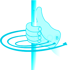
    Right-hand thumb rule:

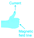
    According to the right-hand thumb rule, if you curl the fingers of the right hand in the direction of the current, the direction of the thumb gives the direction of the induced magnetic field.

    Force on Current-Carrying wire in Magnetic Force

    • The magnetic force on a current-carrying wire is given by:


    F = I L B Sin θ

    Where I is current in the wire, L is the length of the wire, B is the magnetic field and θ is the angle between current and magnetic field.

    Explanation:

    So, we have the expression

    \(B = \frac{μ_0I}{2π r}\)

    Here, from the expression, we can see that. the magnetic field is directly proportional to the current in the conductor for a given distance as  μ and π are constant. 

    So, The strength of the magnetic field will increase at a given point if we increase the magnitude of current in the conductor. This statement is correct. 

    Also, The direction can be obtained from right-hand thumb rule is true. 

    Now, if the current is the same, we can say that

    \(B \propto \frac{1}{r}\)

    The field is inversely proportional to the distance from the point. 

    So, The strength of the magnetic field will be reduced as we move ahead from the conductor for the same current. So, the statement 'The strength of the magnetic field will be more as we move ahead from the conductor for the same current.' is wrong.  

    The next statement to be considered is 

    If another current-carrying conductor is placed near a given conductor, it will experience a force. This is because of the magnetic field presence due to the initial current carrying wire. 

    So, this statement 'If another current carrying conductor is placed near given conductor, it will experience a force.' is also true.

  • Question 5
    1 / -0.25

    A 300 mm long conductor is carrying a current of 10 A and is situated at right angles to a magnetic field having a flux density of 0.8 T; the force on the conductor will be

    Solution

    Given that, current (I) = 10 A

    Magnetic flux density (B) = 0.8 T

    Length of conductor (l) = 300 mm = 0.3 m

    Angle between conductor and magnetic field (θ) = 90°

    The force on the conductor = Bil sin θ = 0.8 × 10 × 0.3 × sin 90° = 2.4 N

  • Question 6
    1 / -0.25
    A moving coil galvanometer can be converted into a ammeter by connecting to the moving coil galvanometer 
    Solution

    CONCEPT:

    • galvanometer can be converted into an ammeter by connecting a shunt resistance in parallel to it.
    • The shunt resistance should have very low resistance. So, the ammeter (the parallel combination of galvanometer and shunt resistance) will have low resistance.
    • To convert a galvanometer into an ammeter of current rating ‘I’, a small resistance ‘S’ (shunt resistance) is connected in parallel across the galvanometer.

    \({V_g} = \left( {I - {I_g}} \right)S = {I_g}{R_g}\)

    Where Vg is the voltage across the galvanometer, I is current in the circuit, Ig is the current is galvanometer, Rg is the resistance of galvanometer and S is the resistance of the shunt.

    EXPLANATION:

    • A moving coil galvanometer can be converted into a ammeter by connecting a low resistance in in parallel to the moving coil galvanometer. So option 2 is correct.
  • Question 7
    1 / -0.25
    Current sensitivity of a moving coil galvanometer is 5 div/mA and its voltage sensitivity (angular deflection per unit voltage applied) is 20 div/V. The resistance of the galvanometer is
    Solution

    CONCEPT:

    • Galvanometer: The instrument which is used to measure and determine the direction of electric current in a magnetic field is called a Galvanometer.
      • It consists of a coil having an electric current.
    • The ratio of change in deflection of a galvanometer to the change in current is called the current sensitivity of the galvanometer.
    • The angular deflection per unit voltage applied is called a voltage sensitivity of the galvanometer.

    The sensitivity of Galvanometer is given by:

    Current sensitivity of galvanometer (Si) = dθ/di = NBA/K

    Voltage sensitivity (SV) = Si/R

    Where N is a number of turns, B is the magnetic field, A is the area of the coil and K is constant, dθ is change in deflection and dI is change in current and R is resistance.

    CALCULATION:

    Given that:

    Current sensitivity (Si) = 5 div/ (m A) = 5 × 10³ div/A

    Voltage sensitivity (SV) = 20 div/V

    Since Voltage sensitivity (SV) = Si/R

    Resistance (R) = SI/ SV = (5 × 10³ div/A)/ (20 div/V) = 250 Ω

    So option 3 is correct.

  • Question 8
    1 / -0.25
    If currents in two parallel wires flow in opposite directions, the force between the wires will be
    Solution

    CONCEPT:

    Magnetic field:

    • The space or region around the current-carrying wire/moving electric charge or around the magnetic material in which force of magnetism can be experienced by other magnetic material is called as magnetic field/magnetic induction by that material/current.
    • It is denoted by B.
    • The magnetic force per unit length between two parallel wires is given by;

    \(\frac{F}{l} = \frac{{{\mu _o}}}{{2\pi }}\frac{{2{I_1}{I_2}}}{d}\)

    Where μ0 = permittivity of free space, I1 = current in a first wire, I2 = current in a second wire,d = distance between two wires, and l = length of current-carrying wire.

    EXPLANATION:​ 

    • The magnetic force per unit length between two parallel wires is given by;

    \(\Rightarrow \frac{F}{l} = \frac{{{\mu _o}}}{{2\pi }}\frac{{2{I_1}{I_2}}}{d}\)

    • If the conductor carries the current in the same direction, then the force between them will be attractive.
    • If the conductor carries the current in the opposite direction, then the force between them will be repulsive. Therefore option 2 is correct.
  • Question 9
    1 / -0.25
    A charge moves in a circle perpendicular to a magnetic field. Upon which of the following the time period of revolution, does not depend?
    Solution

    A particle of mass m and charge q is moving in a circular path with constant speed v in a perpendicular uniform magnetic field B as shown in the figure.

    Force act on moving charged particle due to magnetic field B:

    Fm = Bqv sin θ

    Fm = Bqv

    magnetic force \({F_m} = \frac{{m{v^2}}}{r}\)

    \(Bqv = \frac{{m{v^2}}}{r}\)

    \(r = \frac{{mv}}{{qB}}\)

    now, Time period \(T = \frac{{2\pi }}{\omega },\;\omega = \frac{v}{r}\)

    \(v = \frac{{qBr}}{m}\)

    \(\therefore \omega = \frac{{qB}}{m}\)

    \(Now\;T = \frac{{2\pi m}}{{qB}}\)

    \(T \propto \frac{m}{{qB}}\)

    So this does not depend on the velocity of a particle.
  • Question 10
    1 / -0.25
    A charge particle is moving on a circular path of radius R in a uniform magnetic field under the Lorentz force F. How much work is done by the force in one round?
    Solution

    CONCEPT:

    • Lorentz force: The fundamental force on an electric charge q moving with velocity v in a magnetic field B is called the magnetic Lorentz force.

    We can say that, Lorentz magnetic force (F),

    F = q v B, where q is charge, v = velocity of particle, B = magnetic field.

    \(d\vec r\) = it is a small displacement of particle always perpendicular to the Lorentz magnetic force; that is θ = 90°

    So,  work done by the particle is:

    \(d\vec W\) = F. \(d\vec r\)  = F. dr cos 90° = 0.

    dW = 0. So work done is zero.

    EXPLANATION:

    • Lorentz magnetic force provides the required centripetal force for its circular motion.
    • It means the Lorentz force acts along the radius towards the center of the circular path.


    So, the angle between force and displacement becomes 90°, so the work done is zero. So option 4 is correct. 

Self Studies
User
Question Analysis
  • Correct -

  • Wrong -

  • Skipped -

My Perfomance
  • Score

    -

    out of -
  • Rank

    -

    out of -
Re-Attempt Weekly Quiz Competition
Self Studies Get latest Exam Updates
& Study Material Alerts!
No, Thanks
Self Studies
Click on Allow to receive notifications
Allow Notification
Self Studies
Self Studies Self Studies
To enable notifications follow this 2 steps:
  • First Click on Secure Icon Self Studies
  • Second click on the toggle icon
Allow Notification
Get latest Exam Updates & FREE Study Material Alerts!
Self Studies ×
Open Now