KEY CONCEPTS
RLC circuit
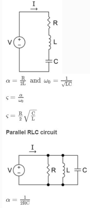
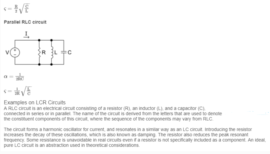
Introduction: An RLC circuit (or LCR circuit or CRL circuit or RCL circuit) is an electrical circuit consisting of a resistor, an inductor, and a capacitor, connected in series or in parallel. The RLC part of the name is due to those letters being the usual electrical symbols for resistance, inductance and capacitance respectively. The circuit forms a harmonic oscillator for current and will resonate in a similar way as an LC circuit will. The main difference that the presence of the resistor makes is that any oscillation induced in the circuit will die away over time if it is not kept going by a source. This effect of the resistor is called damping. The presence of the resistance also reduces the peak resonant frequency somewhat. Some resistance is unavoidable in real circuits, even if a resistor is not specifically included as a component. An ideal, pure LC circuit is an abstraction for the purpose of theory. Resonance: resonance frequency, f0, angular frequency,
Resonance
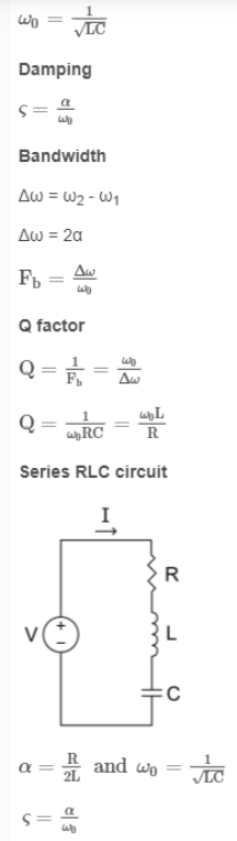
An important property of this circuit is its ability to resonate at a specific frequency, the resonance frequency, ∫0. Frequencies are measured in units of hertz. In this article, however, angular frequency, ω0, is used which is more mathematically convenient. This is measured in radians per second. They are related to each other by a simple proportion,
ω0 = 2π∫0
Generating AC
AC can be produced using a device called an alternator. This device is a special type of electrical generator designed to produce alternating current.
A loop of wire is spun inside of a magnetic field, which induces a current along the wire. The rotation of the wire can come from any number of means: a wind turbine, a steam turbine, flowing water, and so on. Because the wire spins and enters a different magnetic polarity periodically, the voltage and current alternates on the wire.
Waveforms
AC can come in a number of forms, as long as the voltage and current are alternating. If we hook up an oscilloscope to a circuit with AC and plot its voltage over time, we might see a number of different waveforms. The most common type of AC is the sine wave. The AC in most homes and offices have an oscillating voltage that produces a sine wave.
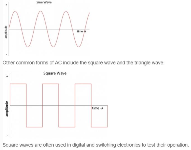
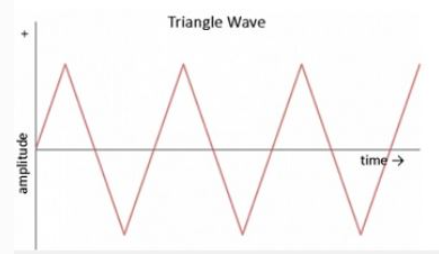
Triangle waves are found in sound synthesis and are useful for testing linear electronics like amplifiers.
Phase relation between voltage and current
Physical quantity which represents both the instantaneous value and direction of alternating quantity at any instant is called it's phase. It's a dimensionless quantity and it's unit is radian.
If an alternating quantity is expressed as X=X0sin (ωt±ϕ0) then the argument of sin(ωt+ϕ) sinωt+ϕ is called it's phase. Where ω t = instantaneous phase (changes with time) and ϕ0 = initial phase (constant w.r.t. time)
Phase difference (Phase constant) : The difference between the phases of currents and voltage is called phase difference. If alternating voltage and current are given by V=V0 sin(ωt+ϕ1) and i=i0 sin(ωt+ϕ2) then phase difference ϕ=ϕ1−ϕ2 (relative to current) or ϕ=ϕ2−ϕ1 (relative to voltage)
Examples on Phase difference, Voltage difference of circuit elements
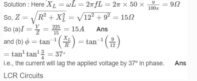
Example. A 9/100π H inductor and a 12 ohm resistance are connected in series to a 225V, 50Hz ac source. Calculate the current in the circuit and the phase angle between the current and the source voltage.
Introduction: An RLC circuit (or LCR circuit or CRL circuit or RCL circuit) is an electrical circuit consisting of a resistor, an inductor, and a capacitor, connected in series or in parallel. The RLC part of the name is due to those letters being the usual electrical symbols for resistance, inductance and capacitance respectively. The circuit forms a harmonic oscillator for current and will resonate in a similar way as an LC circuit will. The main difference that the presence of the resistor makes is that any oscillation induced in the circuit will die away over time if it is not kept going by a source. This effect of the resistor is called damping. The presence of the resistance also reduces the peak resonant frequency somewhat. Some resistance is unavoidable in real circuits, even if a resistor is not specifically included as a component. An ideal, pure LC circuit is an abstraction for the purpose of theory. Resonance: resonance frequency, f0, angular frequency,
Resonance
An important property of this circuit is its ability to resonate at a specific frequency, the resonance frequency, ∫0. Frequencies are measured in units of hertz. In this article, however, angular frequency, ω0, is used which is more mathematically convenient. This is measured in radians per second. They are related to each other by a simple proportion,
ω0 = 2π∫0
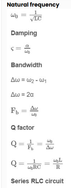
Natural frequency


 ×
×


 Sign in
 Profile
 Signout

