A transistor oscillator is a amplifier with positive feed back.
A transistor oscillator is the one in which DC supply energy is converted into AC output energy.
KEY CONCEPTS
Positive feedback amplifier oscillator
A transistor amplifier with proper positive feedback can act as an oscillator i.e, it can generate oscillations without any external signal source. Fig. 1 shows a transistor amplifier with positive feedback.
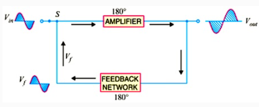
Remember that a positive feedback amplifier is one that produces a feedback voltage that is in phase with the original input signal. As you can see, this condition is met in the circuit shown in fig. A phase shift of ![]() is produced by the amplifier and a further phase shift of
is produced by the amplifier and a further phase shift of ![]() is introduced by feedback network. Consequently, the signal is shifted by
is introduced by feedback network. Consequently, the signal is shifted by ![]() and fed to the input i.e. feedback voltage is in phase with the input signal.
and fed to the input i.e. feedback voltage is in phase with the input signal.
i. We note that the circuit shown in fig. is producing oscillations in the output. However, this circuit has an input signal. This is inconsistent with our definition of an oscillator i.e., an oscillator is a circuit that produces oscillations without any external signal source.
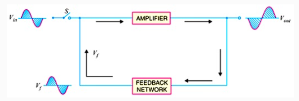
ii. When we open the switch S of Fig. 14.5, we get the circuit shown in Fig. 14.6. This means the input signal. However, Vf (which is in phase with the original signal) is still applied to the input signal. The amplifier will respond to this signal in the same way that it did to Vin i.e., Vf will be amplified and sent to the output. The feedback network sends a portion of the output back to the input. Therefore, the amplifier receives another input cycle and another output cycle is produced. This process will continue so long as the amplifier is turned on. Therefore, the amplifier will produce sinusoidal output with no external signal source. The following points may be noted carefully: (a) A transistor amplifer with proper positive feedback will work as an oscillator. (b) The circuit needs only a quick trigger signal to start the oscillations. Once the oscillations have started, no external signal source is needed. (c) In order to get continuous undamped output from the circuit, the following condition must be met: AvB = 1 where Av = voltage gain of amplifier without feedback B = feedback fraction This relation is called Barkhausen criterion. Fig. shows the block diagram of an oscillator. Its essential components are:
(i) Tank circuit. It consists of inductance coil (L) connected in parallel with capacitor (C). The frequency of oscillations in the circuit depends upon the values of inductance of the coil and capacitance of the capacitor.
(ii) Transistor amplifier: The transistor amplifier receives d.c. power from the battery and changes it into a.c. power for supplying to the tank circuit. The oscillations occurring in the tank circuit are applied to the input of the transistor amplifier. Because of the amplifying properties of the transistor, we get increased output of these oscillations
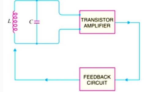
This amplified output of oscillations is due to the d.c. power supplied by the battery. The output of the transistor can be supplied to the tank circuit to meet the losses.
(iii) Feedback circuit: The feedback circuit supplies a part of collector energy to the tank circuit in correct phase to aid the oscillations i.e. it provides positive feedback.
Transistor as an oscillator
(i) The simplest electrical oscillating system consists of an inductance L and a capacitor C connected in parallel.
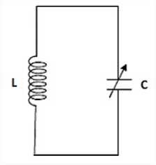
(ii) Once an electrical energy is given to the circuit, this energy oscillates between capacitance (in the form of electrical energy) and inductance (in the form of magnetic energy) with a frequency.
(iii) The amplitude of oscillations is damped due to the presence of inherent resistance in the circuit.
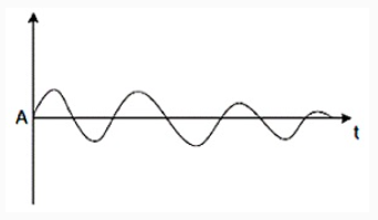
(iv) In order to obtain oscillations of constant amplitude, an arrangement of regenerative or positive feedback from an output circuit to the input circuit is made so that the circuit losses may be compensated.
(v) Circuit diagram of NPN transistor in common emitter configuration as an oscillator.
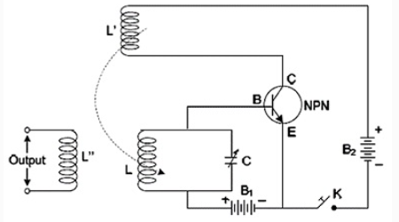
(vi) The tank circuit is used in emitter base circuit of the transistor. The E-B circuit is forward biased whereas the C-B circuit is reverse biased.
(vii) The coil L' in the emitter-collector circuit is inductively coupled with coil L.
(viii) When the key K is closed, IC begins to increase. The magnetic flux linked with coil L' and hence with L also begins to increase. This supports the forward bias pf B-E circuit. As a result of this IE increases. Consequently IC also continues increase till saturation.
(ix) When IC attains saturation value, mutual inductance has no role to play.
(x) When the capacitor begins to discharge through inductance L, the IE and hence IC begins to decrease. Consequently, the magnetic flux linked with L' and hence with L decrease. The forward bias of E-B circuit is opposed thereby further reducing IE and IC. This process continues till IC becomes zero.
(xi) At this stage too, the mutual inductance has once again no role to play.


 ×
×


 Sign in
 Profile
 Signout

