-
Question 1
5 / -1
The magnitude of the energy gap for an insulator is
Solution
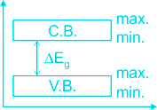
Energy gap between the conduction band and the valence band is known as forbidden energy gap.
Conductors:
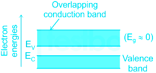
In conductors, the conduction band and the valence band overlap, which indicates that the valence electrons can easily move from the conduction band and are free to conduct.
Insulators:
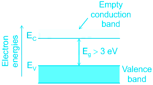
In insulator, there exists a large band gap between conduction band and valence band Eg (Eg > 3 eV), that result in no free electrons in the conduction band, and therefore no electrical conduction is possible.
Semiconductors:
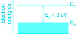
- In semiconductor, there exists a finite but small band gap between conduction band and valence band (Eg < 3 eV).
- Because of the small band gap, at room temperature, some electrons from valence band can acquire enough energy to cross the energy gap and enter the conduction band.
Therefore, the forbidden energy band gap in conductors, semiconductors and insulators are in the relation Eg1 < Eg2 < Eg3.
-
Question 2
5 / -1
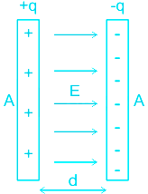
Two point charges of +3q and -q are placed inside a cube of side x. The total electric flux through the cube is _________.
Solution
CONCEPT:
- Flux is a total electric field that passes through the given area.
If we choose a simple surface with area A, the electric flux is:
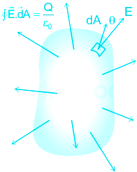
\(ϕ=\oint \overrightarrow{E}.\overrightarrow{dA}\)
where ϕ is the flux, E is the electric field, and dA is the small area.
- Gauss' Law: This law gives the relation between the distribution of electric charge and the resulting electric field.
- According to this law, the total charge Q enclosed in a closed surface is proportional to the total flux ϕ enclosed by the surface.
ϕ α Q
The Gauss law formula is expressed by:
ϕ = Q/ϵ0
- The magnitude of flux ϕ = Q / ϵ0 (if the charge Q is placed at the center of the cube)
CALCULATION:
- The magnitude of flux ϕ = Q / ϵ0 (if the charge Q is placed at the center of the cube)
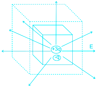
Total charge inside the cube Q = +3q - q = +2q
- Therefore, total flux through the faces of the given cube = 2q/ϵ0
- Hence the correct answer is option 2.
-
Question 3
5 / -1
The level of atmosphere which transmits radio waves is
Solution
The correct answer is Ionosphere.
 Key Points
- The level of the atmosphere used for the transmission of radio waves is the ionosphere.
- The entire atmosphere that is 60 km (80 km somewhere) above the earth about 640 km is called the ionosphere.
- Radio waves transmitted from the Earth are reflected in this circle and return to the earth again.
-
Question 4
5 / -1
If the refractive index of glass is 1, find Brewster’s angle –
Solution
Concept:
Brewster angle –
- The angle of incidence at which a beam of unpolarised light falling on a transparent surface is reflected as a beam of completely plane polarised light is called polarising or Brewster angle. It is denoted by ip.
- The Brirish Physicist David Brewster found the relationship between Brewster angle (ip) and refractive index (μ) –
μ = tan ip - This relation is known as Brewster law.
Explanation:
Given - μ = 1
We know, μ = tan ip
Where ip = Polarization or Brewster’s angle
∴ i
p = tan
-1 μ = tan
-1(1) = 45°
-
Question 5
5 / -1
The ____________ Circuital Law states that, the line integral of the magnetic field around some closed loop is equal to 'μ0' times the algebraic sum of the currents which pass through the loop. ('μo' is the permeability of free space)
Solution
CONCEPT:
- Ampere's Circuital Law: It gives the relationship between the current and the magnetic field created by it.
- This law says that, the integral of magnetic field density (B) along an imaginary closed path is equal to the product of current enclosed by the path and permeability of the medium.
\(\oint \vec B.\overrightarrow {dl} = {μ _0}I\)
Where dl is a small element, μ0 is permeability of free space and I is electric current.
EXPLANATION:
- The ampere's Circuital Law states that, the line integral of the magnetic field around some closed loop is equal to 'μ0' times the algebraic sum of the currents which pass through the loop. So option 1 is correct.
- Biot-Savart's law is the basic law to give the magnetic field by a current element.
- Lorentz's law gives the force on a moving charge in a magnetic field.
- Kirchhoff's law is used to find out the current in an electric circuit.
-
Question 6
5 / -1
Which of the following is not being used for long range communication?
Solution
Correct option is 3.
Concept:
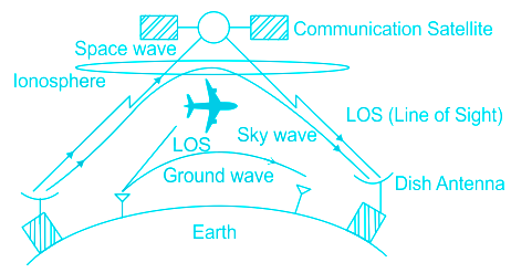
In a communication system, the electromagnetic waves transmitted by the transmitter travels in three different modes to reach the receiver according to its frequency range.
1. Ground wave propagation or surface wave propagation (nearly 2 kHz to 2 MHZ)
2. Sky-wave propagation or ionospheric propagation (nearly 3 MHZ to 30 MHZ)
3. Space wave propagation (nearly 30 MHZ to 400 MHZ)
1. Ground wave propagation:
- If the electromagnetic waves transmitted by the transmitter antenna over the surface of the earth reach the receiver, then the propagation is called ground wave propagation.
- In this mode of transmitting and receiving antennas must be close to the earth's surface.
- During effective transmission through ground wave propagation mobe, electrical signals are attenuated over a distance.
2. Sky-wave propagation:
- In the sky-wave propagation, the electromagnetic wave is radiated from the antenna, directed upwards at large angles gets reflected by the ionosphere back to the earth.
- The frequency range of EM waves in this mode of propagation is 3 to 30 MHZ.
- It is used for short-wave broadcast services medium and high frequencies are for long-distance radio communication.
3. Space wave propagation:
- The process of sending and receiving information signals through space is called space wave communication.
- The EM waves above 30 MHZ frequency traveling from the transmitter to receiver in a straight line are used for line of sight communication (LOS).
Explanation:
Ground waves are not used for long-range communication because -
- As the ground wave passes over the surface of the earth, they are mostly absorbed by its surface this results in the weakening of the transmission signal.
- Due to such loss or attenuation of the signal, ground waves are restricted for long-range communication.
- The figure is given below shows the attenuation of the signal in ground wave propagation.
Hence, option-3 is correct.

- EM waves of frequency above 30 MHZ can easily penetrate through the ionosphere and do not undergo reflection.
- Extremely long-distance communication is also possible as radio waves can undergo multiple reflections between the earth and ionosphere.
- A single reflection helps the radio waves to travel about 4000km.
- The charged ions of the ionosphere provide a reflecting medium for reflection of radio waves or communication waves back to the earth's surface within the permitted frequency range.
- This phenomenon is called the total internal reflection of the EM wave.
-
Question 7
5 / -1
What is the force between two small charged spheres having charges of 2 × 10⁻⁷ C and 3 × 10⁻⁷ C placed 30 cm apart in the air?
Solution
CONCEPT:
Coulomb's law in Electrostatics –
- Coulomb's law state’s that force of interaction between two stationary point charges is directly proportional to the product of the charges, and inversely proportional to the square of the distance between them and acts along the straight line joining the two charges.
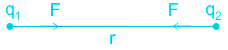
Force (F) ∝ q1 × q2
\(F \propto \;\frac{1}{{{r^2}}}\)
\(F = K\frac{{{q_1} \times {q_2}}}{{{r^2}}}\)
Where K is a constant = 9 × 10⁹ Nm2/C2
EXPLANATION:
Given – q1 = 2 × 10⁻⁷ C, q2 = 3 × 10⁻⁷ C and r = 30 cm = 30 × 10-2 m
Force is equal to
\(F = \left( {9{\rm{\;}} \times {\rm{\;}}{{10}^9}} \right)\times \frac{{2 \times {{10}^{ - 7}} \times 3 \times {{10}^{ - 7}}}}{{{{\left( {30 \times {{10}^{ - 2}}} \right)}^2}}}\)
\( \Rightarrow F = \frac{{54 \times {{10}^{ - 5}}}}{{900 \times {{10}^{ - 4}}}} = 6 \times {10^{ - 3}}N\)
-
Question 8
5 / -1
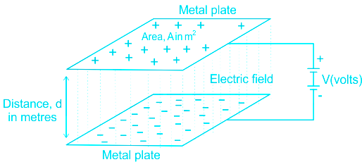
The plate area of a parallel-plate capacitor is 0.01 m2. The distance between the plates is 2.5 cm. If the insulating medium is air, its capacitance will be _________.
Solution
Concept:
The capacitance of a capacitor (C):
The capacitance of a conductor is the ratio of charge (Q) to it by a rise in its potential (V), i.e.
C = Q/V
The unit of capacitance is the farad, (symbol F).
Parallel Plate Capacitor:
A parallel plate capacitor consists of two large plane parallel conducting plates of area A and separated by a small distance d.
The formula for the capacitance of a parallel plate capacitor is given by
\(C = \frac{{A{ϵ_0}}}{d}\)
A = area of the plate
ϵ0 = permittivity of vacuum = 8.85 × 10⁻¹²
d = distance between plate
Calculation:
Given that,
A = 0.01 m2
d = 2.5 cm = 0.025 m
ϵ0 = 8.85 × 10⁻¹²
Now the capacitance of a parallel plate capacitor
\(C = \frac{{0.01 × 8.85 × {{10}^{ - 12}}}}{{0.025}} \)
C = 3.54 pF
-
Question 9
5 / -1
A bulb is marked with 60 W/240 V. The resistance when lighted at 240 V is -
Solution
Concept:
Electric Power:
- The rate of consumption of electrical energy is electric power.
- The SI unit of power is Watt.
- The power dissipated by an electrical device at potential difference across it V, and resistance R is given as
\(P = \frac{V^2}{R}\)
P is power, V is the potential difference, R is resistance
Calculation:
Given Power P = 60 W
Potential difference V = 240 Volt.
Resistance R = ?
\(R = \frac{V^2}{P}\)
\(\implies R = \frac{240^2}{60} \Omega\)
⇒ R = 960 Ω
So, the correct option is 960 Ω.
-
Question 10
5 / -1
The working of Nicol prism is based on the optical phenomenon of _____________.
Solution
Nicol prism:
1). Nicol prism is used for producing a polarised beam of light from an un-polarised beam.
2). It is based on the principle of action which involves refraction as it passes into the lower half of the prism. It leaves the prism as polarised light after undergoing another refraction as it exits the far right side of the prism. Thus its action is based on double refraction.
Double refraction is an optical property in which a single ray of unpolarized light entering an anisotropic medium is split into two rays, each traveling in a different direction.
-
Question 11
5 / -1
Radii of curvature of a converging lens are in the ratio 1 : 2. Its focal length is 6 cm and refractive index is 1.5. Then its radii of curvature are _______ respectively.
Solution
CONCEPT:
- Converging lens: A lens in which light rays enter into it parallel to its axis and converge at a single point on the opposite side.
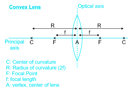
- Radius of curvature: The distance between the vertex and the center of curvature is called the radius of curvature of the surface.
- Focal length: When light passes through a lens, the measure of how strongly the system converges or diverges the light.
- focal length is the inverse of the system's optical power.
- Refractive Index: The ratio of the speed of light in a vacuum and the speed of light in the lens material is called the Refractive Index.
- The focal length of a lens is given by lens maker formula:
\(\frac{1}{f}=(μ-1)(\frac{1}{R_1}-\frac{1}{R_2})\)
where f is the focal length of the lens, μ is the refractive index of the lens, and R1 and R2 are the radiuses of curvature.
CALCULATION:
Given that R1/R2 = 1/2; f = 6 cm; μ = 1.5
2R1 = R2
by lens maker formula
\(\frac{1}{f}=(μ-1)(\frac{1}{R_1}-\frac{1}{-R_2})\)
\(\frac{1}{f}=(μ-1)(\frac{1}{R_1}+\frac{1}{2R_1})\)
\(\frac{1}{f}=(μ-1)(\frac{3}{2R_1})\)
\(\frac{1}{6}=(1.5-1)(\frac{3}{2R_1})\)
R1 = 4.5 cm;
2R1 = R2 = 9 cm;
so the correct answer is option 4.
-
Question 12
5 / -1
Two-point charges of +5μC and +5μC are placed 8 cm apart in the air. Find the distance at which the resultant electric field is zero.
Solution
Concept:
Electric Field Intensity: The electric field intensity at any point is the strength of the electric field at the point.
It is defined as the force experienced by the unit positive charge placed at that point.
\(\vec E = \frac{{\vec F}}{{{q_o}}}\)
Where F = force and qo = small test charge
The magnitude of the electric field (E) is given by:
\(E = \frac{{kq}}{{{r^2}}}\)
Where K = constant called electrostatic force constant
q = source charge
r = distance
Calculation:
Given that: Distance between two charges (r) = 8 cm
Charges on each (q) = + 5 μC
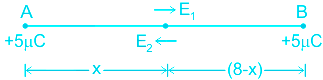
Let P be the point at distance x from A, where the net electric field is zero.
The electric field at P due to A is
\({E_1} = \frac{{k\; \times \;5\; \times \;{{10}^{ - 6}}}}{{{x^2}}}\)
The electric field at P due to B is
\({E_2} = \frac{{k\; \times\; \left( { 5\; \times \;{{10}^{ - 6}}} \right)}}{{{{\left( {8\; - \;x} \right)}^2}}}\)
At point P, E1 - E2 = 0
E1 = E2
\( \frac{{k\; \times \;5\; \times \;{{10}^{ - 6}}}}{{{x^2}}} = \frac{{k\; \times \;5\; \times \;{{10}^{ - 6}}}}{{{{\left( {8\; -\; x} \right)}^2}}}\)
\( \frac{1}{{{x^2}}} = \frac{1}{{{{\left( {8\; - \; x} \right)}^2}}}\)
By square rooting both side, we get:
x = 8 - x
2x = 8
x = 4 cm
-
Question 13
5 / -1
When a beam of ordinary light is passed through a calcite crystal, the light splits into O-ray and E-ray inside the crystal.
Solution
When ordinary light is allowed to pass through calcite or quartz, it splits into two refracted beams(O-ray & E –ray) and both are plane-polarized lights.
Polarisation:
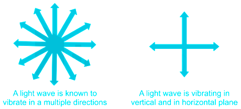
- The phenomenon due to which vibrations of light waves are restricted in a particular plane is called polarisation.
- In an ordinary beam of light from a source, the vibrations occur normal to the direction of propagation in all possible planes. Such a beam of light called unpolarised light.
- If by some methods (reflection, refraction, or scattering) a beam of light is produced in which vibrations are confined to only one plane, then it is called plane polarised light.
- Hence, polarization is the phenomenon of producing plane polarised light from unpolarised light.
 Additional Information
There are three types of polarized light
- Plane Polarized Light
- Circularly Polarized Light (O-ray)
- Elliptically Polarized Light (E-ray)
-
Question 14
5 / -1
What is the value of the collector current of a bipolar junction transistor having a current gain (β) of 200 and the base current of 50 μA?
Solution
Concept:
The common-emitter current gain is the ratio of the value of the transistor's collector current to the value of the transistor's base current in a transistor, i.e.
\(β = \frac{{{I_C}}}{{{I_B}}}\)
IC = β IB
Calculation:
With β = 200 and IB = 50 μA, the collector current will be:
IC = β IB = 200 × 50 μA
IC = 10000 μA = 10 mA
IC = 10 mA
Note:
The common base DC current gain is a ratio of the value of the transistor's collector current to the value of the transistor's emitter current, i.e.
\(α = \frac{{{I_C}}}{{{I_E}}}\)
For a transistor, the relation between the collector, base, and emitter current is:
IE = IB + IC
-
Question 15
5 / -1
Same amount of charges are given to two capacitors A and B from the sources of emfs 100V and 150V, respectively, then the ratio of their capacitances is_______.
Solution
CONCEPT:
- Capacitor: A capacitor is a device that stores electrical energy in an electric field.
- It is a passive electronic component with two terminals.
- The effect of a capacitor is known as capacitance.
- Capacitance: The capacitance is the capacity of the capacitor to store charge in it. Two conductors are separated by an insinuator (dielectric) and when an electric field is applied, electrical energy is stored in it as a charge.
- The capacitance of a capacitor (C): The capacitance of a conductor is the ratio of charge (Q) to it by a rise in its potential (V), i.e.
C = Q/V
- The unit of capacitance is the farad, (symbol F ).
- Farad is a large unit so generally, we using μF.
CALCULATION:
Given - Let charge on each capacitor be Q (let), the voltage across capacitor A = 100 V, and the voltage across capacitor B = 150 V
- The capacitance of capacitor A is
\(\Rightarrow C_A=\frac{Q}{V}=\frac{Q}{100}\) ----- (1)
- The capacitance of capacitor B is
\(\Rightarrow C_B=\frac{Q}{V}=\frac{Q}{150}\) ----- (2)
On dividing equation 1 and 2, we get
\(\Rightarrow \frac{C_A}{C_B}=\frac{150}{100}=\frac{3}{2}\)
-
Question 16
5 / -1
The net electric flux through a spherical surface having 10 μC charge at the centre is
Solution
The correct answer is option 2) i.e. \(\frac{10\; × \;10^{-6}}{\epsilon_0}\) Vm
CONCEPT:
- Gauss's Law for electric field: It states that the total electric flux emerging out of a closed surface is directly proportional to the charge enclosed by this closed surface. It is expressed as:
\(ϕ = \frac{q}{ϵ_0}\)
Where ϕ is the electric flux, q is the charge enclosed in the closed surface and ϵ0 is the permittivity of free space
EXPLANATION:
- The charge, q = 10 μC = 10 × 10-6 C
From Gauss's law, electric flux \(ϕ = \frac{q}{ϵ_0} = \frac{10 \;\times \;10^{-6}}{ϵ_0} \:{Vm}\)
-
Question 17
5 / -1
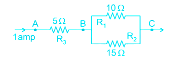
In the given circuit, current through 10 Ω resistor is:
Solution
Concept:
The current at junction B will divide into two branches:
Current through R1
\({I_1} = I\frac{{{R_2}}}{{{R_1} + {R_2}}}\)
Current through R2
\({I_2} = I\frac{{{R_1}}}{{{R_1} + {R_2}}}\)
Calculation:
Current through 10 Ω resistor is given by
\({I_1} = I\frac{{{R_2}}}{{{R_1} + {R_2}}} = 1\left( {\frac{{15}}{{15 + 10}}} \right) = \frac{{15}}{{25}} = 0.6\;A\)
-
Question 18
5 / -1
In a bi-prism experiment, the interference pattern is observed at a distance of 15 cm from the source and the wavelength of light is 400 nm. The distance between two virtual sources is 2 mm. Find the fringe width of pattern.
Solution
CONCEPT:
- Fresnel Bi-prism: It is an optical device of producing interference of light by joining two base thin prism at very small angle.
- When a monochromatic light source is kept in front of bi-prism two coherent virtual sources are produced.
- The Interference fringes are produced behind the bi-prism in limited area and can see with the help of eye piece.
- Fringe width will be calculated with simple calculations.
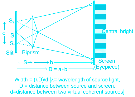
- Width = (λ D)/d [λ = wavelength of source light, D = distance between source and screen, d = distance between two virtual coherent sources]
CALCULATION:
Given, D = 15 cm = 15 × 10-2 m, d = 2 mm = 2 × 10⁻³ m, λ = 400 × 10-9 m
Width = (λ D)/d
\(width = \frac{{400 \times {{10}^{ - 9}} \times 15 \times {{10}^{ - 2}}}}{{2 \times {{10}^{ - 3}}}}\; = 3 \times {10^{ - 5}}m = 0.03\;mm\;\)
-
Question 19
5 / -1
A coil of an area of 2 m2 is placed in a magnetic field that changes from 4 wb/m2 to 8 wb/m2 in 2 seconds. Find the induced emf in the coil.
Solution
CONCEPT:
Faraday's first law of electromagnetic induction:
- Whenever a conductor is placed in a varying magnetic field, an electromotive force is induced.
- If the conductor circuit is closed, a current is induced which is called induced current.
Faraday's second law of electromagnetic induction:
- The induced emf in a coil is equal to the rate of change of flux linked with the coil.
\(⇒ e=-N\frac{d\text{ }\!\!\Phi\!\!\text{ }}{dt}\)
Where N = number of turns, dΦ = change in magnetic flux and e = induced e.m.f.
- The negative sign says that it opposes the change in magnetic flux which is explained by Lenz law.
EXPLANATION:
Given: Area of the coil (A) = 2 m2, initial magnetic field (B1) = 4 wb/m2, Final magnetic field (B2) = 8 wb/m2 , and time (t) = 2 seconds
- According to Faraday’s second law of electromagnetic induction.
\(⇒ E = \frac{{d\phi }}{{dt}}=\frac{d(BA)}{dt}=A\frac{dB}{dt}\)
\(⇒ E = A\frac{{dB}}{{dt}}\)
\(⇒ E= 2\left( {\frac{{8 - 4}}{2}} \right)\)
⇒ E = 4 v
-
Question 20
5 / -1
Half-life of a radioactive element is 30 days, then the remaining amount after 90 days:
Solution
Concept:
As per radioactive decay law, the total number of nuclei of radioactive compounds after radioactive decay in the sample is given by given equation
\(N=N_0 e^{-λ t}\)
where N is the number of nuclei of radioactive compounds after radioactive decay, N0 is the number of nuclei of radioactive compounds initially, λ is the decay constant and t is the time of radioactive decay.
The half-life of a radioactive element (T1/2): The time interval in which the mass of a radioactive substance or the number of atoms reduced to half of its initial value.
The expression for the half-life is
\({T_{\frac{1}{2}}} = \frac{{0.693}}{\lambda }\)
Where λ = is the decay rate constant
Calculation:
Given - T = 90 days, t = 30 days
The number of half-lives (n) in 90 days is:
\(n = \frac{T}{t}=\frac{90}{30}=3 \)
As we know:
\(N=N_o(\frac{1}{2})^n\)
\( N=N_o(\frac{1}{2})^3=\frac{N_o}{8}\)
-
Question 21
5 / -1
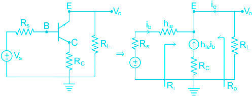
The transistor amplifier in the following configuration is called emitter follower
Solution
Emitter-follower circuit:
- The Emitter-follower circuit is also known as a common collector (CC) configuration.
- It is called the emitter follower configuration because the emitter voltage follows the base voltage.
- Mostly used as a voltage buffer.
- The voltage gain is unity of the Emitter-follower circuit.
- Small signal model & hybrid model is shown below:
Important Differences between different transistor configuration is as shown:
Parameter | Common-Base | Common-Emitter | Common-Collector |
Input Current | IE | IB | IB |
Output Current | IC | IC | IE |
Current Gain | \({\alpha _{dc}} = \frac{{{I_C}}}{{{I_E}}}\) | \({\beta _{dc}} = \frac{{{I_C}}}{{{I_B}}}\) | \(\gamma = \frac{{{I_E}}}{{{I_B}}} \) \({1 + {\beta _{dc}}}\) |
Voltage Gain | Medium | Medium | Less Than 1 |
-
Question 22
5 / -1
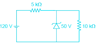
In the figure with Zener diode, the currents through the series resistance and load resistance are respectively
Solution
CONCEPT:
- Zener diode: A Semiconductor diode blocks current in the reverse direction, but will suffer from premature breakdown or damage if the reverse voltage applied across becomes too high.
It can operate continuously without being damaged in the region of reverse biased
Functions:
1) It acts as a voltage regulator
2) In forward biasing it acts as an ordinary diode.
The current flowing through the Zener diode is given by the following formula:
\({{\rm{I}}_{\rm{Z}}} = {{\rm{I}}_{{{\rm{R}}_{\rm{i}}}}} - {{\rm{I}}_{{{\rm{R}}_{\rm{L}}}}}\)
CALCULATION:
When the power supply is 120 V,
Here zener voltage = 50 V
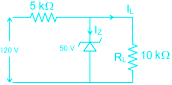
The voltage across 5 KΩ is:
VRi = Power supply – Zener voltage
⇒ VRi = 120 – 50
∴ VRi = 70 V
Now, the current through Ri is:
\({{\rm{I}}_{{{\rm{R}}_{\rm{i}}}}} = \frac{{{{\rm{V}}_{{\rm{Ri}}}}}}{{{{\rm{R}}_{\rm{i}}}}}\)
\(\Rightarrow {{\rm{I}}_{{{\rm{R}}_{\rm{i}}}}} = \frac{70}{{5000}} = 14 mA\)
∴ Current through series resistance = IRi = 14 mA
The voltage across RL is:
VRL = Zener voltage
∴ VRL = 50 V
Now, the current through RL = VRL = 50/10000 = 5 mA
So option 3 is correct
-
Question 23
5 / -1
In a RLC circuit Inductance is 20 mH and capacitance is 200 micro Farad. Find the resonance frequency of the circuit.
Solution
RLC series circuit:
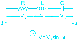
An RLC circuit is an electrical circuit consisting of Inductor (L), Capacitor (C), Resistor (R) it can be connected either parallel or series.
When the LCR circuit is set to resonate (XL = XC), the resonant frequency is expressed as
\(f = \dfrac{1}{{2π }}\sqrt {\dfrac{1}{{LC}}}\;Hz\)
\(\omega = \sqrt {\dfrac{1}{{LC}}}\;rad/sec\)
Quality factor:
The quality factor Q is defined as the ratio of the resonant frequency to the bandwidth.
\(Q=\frac{{{f}_{r}}}{BW}\)
Mathematically, for a coil, the quality factor is given by:
\(Q=\frac{{{\omega }_{0}}L}{R}=\frac{1}{R}\sqrt{\frac{L}{C}}\)
Where,
XL & XC = Impedance of inductor and capacitor respectively
L, R & C = Inductance, resistance, and capacitance respectively
fr = frequency
ω0 = angular resonance frequency
Calculation:
Given, L = 20 mH = 20 × 10-3 H
C = 200 μF = 200 × 10-6 F
\(\omega = \sqrt {\dfrac{1}{{LC}}} =\sqrt {\dfrac{1}{{20\times 10^{-3}\times 200\times10^{-6}}}}=\;500\;rad/sec\)
-
Question 24
5 / -1
The maximum possible mutual inductance between the coils have self inductance L1 = 4 H and L2 = 16 H is ______.
Solution
Concept:
Mutual Inductance
When two coils are placed close to each other, a change in current in the first coil produces a change in magnetic flux, which lines not only the coil itself but also the second coil as well. The change in the flux induced voltage in the second coil. The voltage is called induced voltage and the two coils are said to have a mutual inductance.
The coupling coefficient K represents how closely they are coupled.
We have expression
\(M = K\sqrt {{L_1}{L_2}} \)
Where
M = Mutual inductance
L1 = Inductance of coil one
L2 = Inductance of coil two
Calculation:
Given
L1 = 4 H
L2 = 16 H
K = 1
\(M = K\sqrt {{L_1} \times {L_2}} = 1\sqrt {4 \times 16} = 8\;H\)
For the maximum value of inductance, the value of K must be equal to 1
-
Question 25
5 / -1
Two long straight parallel conductors of length 'L', separated by a distance 'd' and each carrying a current 'I' attract each other with a force equal to
___________.
Solution
Concept:
- Ampere's Circuital Law: It states the relationship between the current and the magnetic field created by it.
- This law states that the integral of magnetic field density (B) along an imaginary closed path is equal to the product of current enclosed by the path and permeability of the medium.
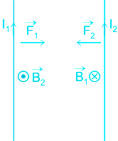
From the Ampere’s circuital law, the magnitude of the field due to the first conductor can be given by,
The force on a segment of length L of the conductor 2 due to the conductor 1 can be given as,
\(B=\frac{{{\mu }_{0}}{{I}_{1}}}{2\pi d}\)
Because of this magnetic field, the force exerted due to magnetic field of conductor 1 on conductor 2 can be expressed as
\(F={{B}_{1}}{{I}_{2}}L=\frac{{{\mu }_{0}}{{I}_{2}}{{I}_{1}}}{2\pi d}L\)
If the current is flowing in the opposite direction, the force between them is repulsive. But the magnitude in both cases is the same.
Here,
F = force exerted
I1 = amount of current in wire 1
I2 = amount of current in wire 2
L = length of wire
d = distance of separation
Explanation:
From the above explanation, we can see that the force exerted by two current-carrying wire can be expressed as
\(F=\frac{{{\mu }_{0}}{{I}_{2}}{{I}_{1}}}{2\pi d}L\)
And if both conductors carrying the same current I the above equation can be expressed as
\(F=\frac{{{\mu }_{0}}{{I}^{2}}}{2\pi d}L\)
-
Question 26
5 / -1
The magnification of a convex mirror is +2. If the height of the object is 10 cm, then height of the image will be-
Solution
The correct answer is option 1) i.e, +20cm.
CONCEPT:
- Magnification of a spherical mirror: Magnification is a measure of the size of the image formed as compared to the size of the object.
- It is the ratio of the height of the image(hi) to the height of the object(ho)
It is given by the formula:
\(M = \frac {h_{i}}{h_{o}}\)
- A positive value of magnification signifies a virtual image whereas, a negative value signifies a real image.
- Magnification of value greater than 1 signifies enlarged image whereas, magnification of value less than 1 signifies diminished image.
CALCULATION:
Given data,
Magnification, M = +2
Height of the object, ho = 10cm
To find the height of the image, hi
We know that,
\(M = \frac {h_{i}}{h_{o}}\)
⇒ +2 = hi/10
⇒ hi = +20cm
-
Question 27
5 / -1
If kinetic energy of two electrons is in the ratio of 4 : 1, find the ratio of associated de-Broglie wavelength respectively.
Solution
CONCEPT:
- de Broglie wavelength of electrons: Louis de Broglie theorized that not only light possesses both wave and particle properties, but rather particles with mass - such as electrons - do as well.
- The wavelength of material waves is also known as the de Broglie wavelength.
- de Broglie wavelength (λ) of electrons can be calculated from Planks constant h divided by the momentum of the particle.
λ = h/p
where h is Plank's const, λ is de Broglie wavelength, and p is the momentum.
- In terms of Kinetic energy, de Broglie wavelength of electrons:
\(λ=\frac{h}{\sqrt{2mE}}\)
where λ is de Broglie wavelength, m is the mass of an electron, h is Plank's const, and E is the energy of the electron.
CALCULATION:
Given that E1 : E2 = 4 : 1
\(λ_1=\frac{h}{\sqrt{2mE_1}}\) ......(i)
\(λ_2=\frac{h}{\sqrt{2mE_2}}\) ......(ii)
\(\frac{λ_1}{λ_2}=\sqrt\frac{E_2}{E_1}=\sqrt\frac{1}{4}=\frac{1}{2}\)
So the correct answer is option 4.
-
Question 28
5 / -1
Which of the following device is not a part of detector system of amplitude modulated wave?
Solution
CONCEPT:
Detection of amplitude modulated wave:
- The transmitted message gets attenuated in propagating through the channel.
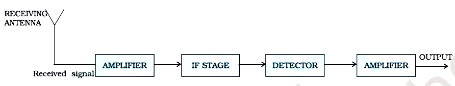
- The receiving antenna is, therefore, to be followed by an amplifier and a detector.
- In addition, to facilitate further processing, the carrier frequency is usually changed to a lower frequency by what is called an intermediate frequency (IF) stage preceding the detection.
- The detected signal may not be strong enough to be made use of and hence is required to be amplified.
- A block diagram of a typical receiver is shown in the below-given figure,
- Detection is the process of recovering the modulating signal from the modulated carrier wave.
- We know that the modulated carrier wave contains the frequencies ωc, (ωc - ωm) and (ωc + ωm).
- In order to obtain the original message signal m(t) of angular frequency ωm, a simple method that is shown in the form of a block diagram is used,
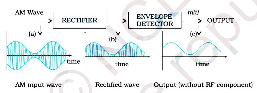
- The modulated signal of the form given in (a) of the above figure is passed through a rectifier to produce the output shown in (b).
- This envelope of signal (b) is the message signal. In order to retrieve m(t ), the signal is passed through an envelope detector (which may consist of a simple RC circuit).
EXPLANATION:
- From the above explanation, it is clear that a rectifier and an envelope detector is part of the detector system of an amplitude-modulated wave.
- But amplifier is not a part of this system. Hence, option 3 is correct.
-
Question 29
5 / -1
Magnetic moment of a current carrying loop can be increased by which of the following?
Solution
CONCEPT:
- Magnetic moment (μ): The magnetic strength and orientation of a magnet or other object that produces a magnetic field.
- It is a vector quantity associated with the magnetic properties of electric current loops.
- It is equal to the amount of current flowing through the loop multiplied by the area encompassed by the loop.
μ = N i A
where μ is the magnetic moment, A is the area of the coil, N is no. of turns and I is current in the coil.
EXPLANATION:
Magnetic dipole moment in a circular loop is given by:
μ = N i A
μ α N
- So as the number of turns increases, the magnetic moment of the circular loop will also increase.
μ α i
- So as current i increases, the magnetic moment of the circular loop will also increase.
μ α A
- So as the area increases, the magnetic moment of the circular loop will also increase.
- The magnetic moment of a current-carrying loop is independent of the magnetic field present due to other magnets.
- Hence the correct answer is option 1.
-
Question 30
5 / -1
Arrange paramagnetic, diamagnetic, and ferromagnetic material on the order of susceptibility?
Solution
CONCEPT:
- Magnetic susceptibility (χm): It is the property of the substance which shows how easily a substance can be magnetized.
- It is defined as the ratio of the intensity of magnetization (I) in a substance to the magnetic intensity (H) applied to the substance, i.e. \(\chi = \frac{I}{H}\)
- It is a scalar quantity with no units and dimensions.
Explanation:
Diamagnetic Substance:
- Diamagnetic substances are those which develop feeble magnetization in the opposite direction of the magnetizing field.
- Such substances are feebly repelled by magnets and tend to move from stronger to weaker parts of a magnetic field.
- Magnetic susceptibility is small and negative i.e. -1 ≤ χ ≤ 0.
- Examples: Bismuth, copper, lead, zinc, etc.
Paramagnetic substances:
- Paramagnetic substances are those which develop feeble magnetization in the direction of the magnetizing field.
- Such substances are feebly attracted by magnets and tend to move from weaker to stronger parts of a magnetic field.
- Magnetic susceptibility is small and positive i.e. 0 < χ.
- Example: Manganese, aluminum, chromium, platinum, etc.
Ferromagnetic substances:
- Ferromagnetic substances are those which develop strong magnetization in the direction of the magnetizing field.
- They are strongly attracted by a magnet and tend to move from weaker to the stronger part of a magnetic field.
- Magnetic susceptibility is very large and positive i.e. χ > 1000
- Example: Iron, cobalt, nickel, gadolinium, and alloys like alnico.
- From above it clear that the susceptibility of the Ferromagnetic material > Paramagnetic material > Diamagnetic material. Thus option 4 is correct.
-
Question 31
5 / -1
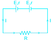
Five cells, each with an e.m.f. of 2V and internal resistance of 0.5 Ω are connected in series. The resulting battery will have
Solution
Concept:
Series grouping: In series grouping anode of one cell is connected to the cathode of other cells and so on.
If n identical cells are connected in series
1. Equivalent emf of the combination Eeq = nE
2. Equivalent internal resistance req = nr
Parallel grouping: In parallel grouping, all anodes are connected at one point and all cathode are connected together at other points.
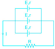
If n identical cells are connected in parallel
1. Equivalent emf of the combination Eeq = E
2. Equivalent internal resistance req = r/n
Calculation:
Here all five (E = 2 V ) are connected in series combination:
So equivalent voltage = 5E = 10 V
equivalent resistance = 5r = 5 × 0.5 = 2.5 Ω
-
Question 32
5 / -1
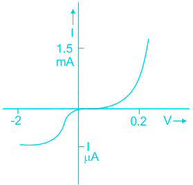
Which is the correct graph for reverse bias current through a photodiode?
Solution
CONCEPT:
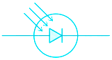
- Photodiode: A photodiode is a p-n junction fabricated from a photosensitive semiconductor and provided with a transparent window to allow light to fall on its junction.
- It is represented by
EXPLANATION:
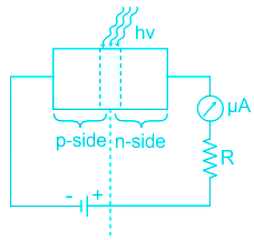
- A resistance R is connected in series with a reverse-biased photodiode. The voltage is kept slightly less than the breakdown voltage.
- When no light is incident on the junction, a small reverse saturation flows through the junction. This reverse current is due to thermally generated electron-hole pairs and is called dark current.
- When a photodiode is illuminated with a large photon of energy hν > Eg, and incrsesing intensities I1, I2, and I3, etc. The value of reverse saturation current increases with the increase in the intensity of incident light. Therefore option 1 is correct.
-
Question 33
5 / -1
209Bi83 → ATi81 + α particle. What is the value of 'A'?
Solution
CONCEPT:
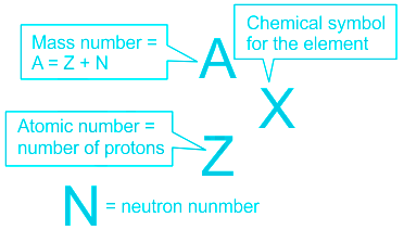
- In nucleus of an atom there are protons and neutrons.
- Number of protons = Atomic number of an element.
- Nuclei = neutron + proton
- The number of protons and number of electrons are equal in a neutral atom.
Radioactive nuclear decay: Radioactive nuclear decay is the process by which an unstable isotope of a particular element spontaneously transforms into a new element by the emission of ionizing radiation. Example: Decay of C-14 to C-12.
- α-decay: An alpha particle consists of two protons and two neutrons, which is a helium nucleus. Losing the protons and neutrons makes the nucleus more stable.
- β-decay: Beta decay is a type of radioactive decay in which a beta particle (fast energetic electron or positron) is emitted from an atomic nucleus.
- γ-decay: it neither changes the atomic number nor atomic mass.
EXPLANATION:
From the above explanation, we can see that in alpha decay one helium atom is ejected from an atom
i.e., AXZ → A-4XZ-2 + 4He2
Hence in our case, the value of A can be predicted by equating the number of nucleons before and after alpha-decay
i.e., 209 = A + 4 ⇒ A = 205
Thus the reaction can be expressed as
209Bi83 → 205Ti81 + α
Which means 1 is correct among all
-
Question 34
5 / -1
When glass rod is rubbed with silk, the charge on silk cloth by convention
Solution
Concept:
- Electric charge: When two objects are rubbed, both acquire charge.
- Electric charges are of two types, positive and negative.
- When two objects are rubbed, one acquires a positive charge and another acquires a negative charge.
- Like charges attract and unlike charges repel each other.
- By convention, when the glass rod is rubbed with the silk, the glass rod acquires a positive charge and silk acquires a negative charge.
Explanation:
- A glass rod when rubbed with silk, it acquires a positive charge.
- It will repeal the positive charge, and attract the negative charge.
- Silk will acquire a negative charge. This has been assumed by convention.
Additional Information
- The SI unit of charge is Coulomb. This has been named after Charles-Augustin de Coulomb.
- An electron or proton has 1.602 × 10 - 19 C of charge. Charge on electron is negative while charge on Proton is positive.
- Charge is additive
- Charge is quantized
- Charge is conserved.
- Flow of charge per unit time is called electric current
-
Question 35
5 / -1
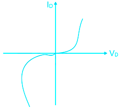
In forward region of its characteristics, a diode appears as
Solution
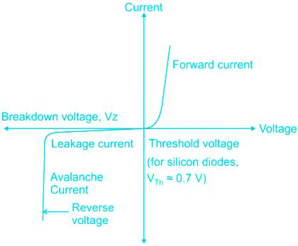
Diode characteristic curve is a plot between voltage and current.
In forward bias, the diode appears as ON switch.
 Important Points
In reverse-bias, the diode prohibits current and only very small amount of current flows, called reverse saturation current.After certain reverse voltage called reverse breakdown voltage the diode breaks down and conducts huge current.
-
Question 36
5 / -1
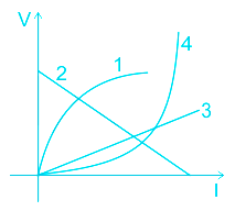
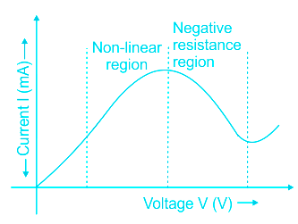
Which of the following graph follows Ohm's law
Solution
CONCEPT:
Ohm's law:
- A conductor through which a current I is flowing and let V be the potential difference between the ends of the conductor. Then Ohm’s law states that
⇒ V ∝ I
⇒ V = IR
where R is called the resistance of the conductor. Resistance depends on the shape, size, and material of the conductor.
Limitations of Ohm's law:
- Ohm’s law is valid over a large class of materials.
- There do exist materials and devices used in electric circuits where the proportionality of V and I does not hold.
The deviations in occurring are one or more of the following types:
- V is not to be proportional to I for some range of V or I
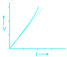
- The relation between V and I depends on the sign of V.
- Reversing the direction of V keeping its magnitude fixed does not produce a current of the same magnitude as I in the opposite direction.
- The relation between V and I is not unique
- There is more than one value of V for the same current I
EXPLANATION:
Ohm's law:
- A conductor through which a current I is flowing and let V be the potential difference between the ends of the conductor. Then Ohm’s law states that
⇒ V ∝ I
⇒ V = RI
where R is called the resistance of the conductor. Resistance depends on the shape, size, and material of the conductor.
- This equation is that of a straight line
⇒ y = mx + c
where y = V, m = R, x = I, c = 0
- Graph that is a straight line passing through origin with a positive slope follows ohms law, that is 3. Therefore option 3 is correct.
Important Points
- There are conditions when Ohm's law is not valid.
-
Question 37
5 / -1
Why can't we explain the photoelectric effect by the wave theory of light?
Solution
CONCEPT:
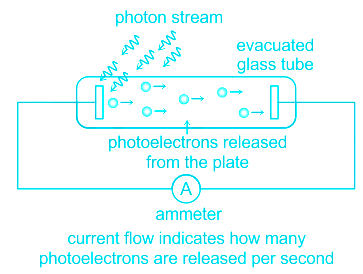
Photoelectric Effect:
- When the light of a sufficiently small wavelength is incident on the metal surface, electrons are ejected from the metal instantly. This phenomenon is called the photoelectric effect.
- Einstein’s equation of photoelectric effect:
⇒ KEmax = hν - ϕo
Where h = 6.63×10⁻³⁴ J-sec = Planck's constant, ν = frequency of incident radiation, ϕo = work function, and KEmax = maximum kinetic energy of electrons.
EXPLANATION:
Photoelectric effect and wave theory of light:
- The phenomena of interference, diffraction, and polarisation were explained in a natural and satisfactory way by the wave picture of light.
- According to this picture, light is an electromagnetic wave consisting of electric and magnetic fields with a continuous distribution of energy over the region of space over which the wave is extended.
- According to the wave picture of light, the maximum kinetic energy of the photoelectrons on the surface of the metal is expected to increase with the increase in intensity.
- Also, no matter what the frequency of radiation is, a sufficiently intense beam of radiation (over sufficient time) should be able to impart enough energy to the electrons so that they exceed the minimum energy needed to escape from the metal surface.
- A threshold frequency, therefore, should not exist.
- But the experimental results show that the maximum kinetic energy of the photoelectrons does not depend on the intensity of radiation and the minimum frequency is required for the photoelectric effect.
- The minimum frequency that is required for the photoelectric effect is called the threshold frequency.
- The experimental results show that the maximum kinetic energy of the photoelectrons does not depend on the intensity of radiation.
- Further, we should note that in the wave picture, the absorption of energy by electrons takes place continuously over the entire wavefront of the radiation.
- Since a large number of electrons absorb energy, the energy absorbed per electron per unit time turns out to be small.
- Explicit calculations estimate that it can take hours or more for a single electron to pick up sufficient energy to overcome the work function and come out of the metal.
- But the experimental results show that the photoelectric emission is instantaneous.
- From the above explanation, we can say that the wave picture is unable to explain the most basic features of photoelectric emission. Hence, option 3 is correct.
-
Question 38
5 / -1
At a certain place, the horizontal component of the earth's magnetic field is √3 times the vertical component. The angle of dip at that place is
Solution
CONCEPT:
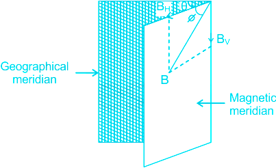
The horizontal component of the earth's magnetic field (BH) –
- Earth's magnetic field is horizontal only at the magnetic equator.
- At any other place, the total intensity can be resolved into a horizontal component (BH) and vertical component (BV).
The horizontal component (BH) is BH = B cos Φ ------ (1)
The vertical component (BV) is BV = B sin Φ ------ (2)
By squaring and adding equation 1 and 2, we get
BH + BV = (B cos θ)2 + (B sin θ)2
∴ The total magnetic field intensity is
\( \Rightarrow B = \sqrt {B_H^2 + B_V^2} \)
Divide equation 2 with 1, we get
\(\frac{{{B_V}}}{{{B_H}}} = \frac{{\sin {\rm{\Phi }}}}{{\cos {\rm{\Phi }}}} = \tan {\rm{\Phi }}\)
\(\therefore \tan {\rm{\Phi }} = \frac{{{B_V}}}{{{B_H}}}\)
EXPLANATION:
Given – BH = √3 BV
As we know that the angle of dip at that place is given by
\(\tan {\rm{\Phi }} = \frac{{{B_V}}}{{{B_H}}}\)
\(\therefore \tan {\rm{\Phi }} = \frac{{{B_V}}}{{{B_V}\sqrt 3 }} = \frac{1}{{\sqrt 3 }}\)
⇒ Φ = 30°
∴ The angle of dip at that place is 30°.
-
Question 39
5 / -1
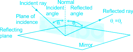
Which of the following is Incorrect regarding the laws of reflection?
Solution
Concept:
Reflection: The phenomena in which light ray is sent back into the same medium from which it is coming, on interaction with boundary, is called reflection.
- Laws of reflection: it states that, if a light ray is reflected from a plane flat polished surface its angle of the incident will always be equal the angle of reflection
i.e. The angle of incidence (θ i ) = Angle of reflection (θ r )
Important Points
The incident ray, the reflected ray, and normal to the surface of incidence always lies in the same plane.
The law of reflection is also valid for all curved and spherical surface
Explanation:
The law of reflection is applicable for all spherical objects as we see in convex and concave mirrors.
-
Question 40
5 / -1
Which of the following device converts non electrical signal into electrical form in a communication system?
Solution
CONCEPT:
Elements of a Communication System:
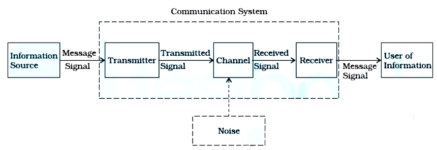
- Irrespective of the nature of the communication system, every communication system has three essential elements:
- Transmitter
- Medium or channel
- Receiver
- In a communication system, the transmitter is located at one place, the receiver is located at some other place (far or near) separate from the transmitter and the channel is the physical medium that connects them.
- Depending upon the type of communication system, a channel may be in the form of wires or cables connecting the transmitter and the receiver or it may be wireless.
- The purpose of the transmitter is to convert the message signal produced by the source of information into a suitable form for transmission through the channel.
- If the output of the information source is a non-electrical signal like a voice signal, a transducer converts it to an electrical form before giving it as an input to the transmitter.
- When a transmitted signal propagates along the channel it may get distorted due to channel imperfection.
- Moreover, noise adds to the transmitted signal and the receiver receives a corrupted version of the transmitted signal.
- The receiver has the task of operating on the received signal. It reconstructs a recognizable form of the original message signal for delivering it to the user of information.
- There are two basic modes of communication:
- Point-to-point
- Broadcast
Point to point communication:
- In point-to-point communication mode, communication takes place over a link between a single transmitter and a receiver.
- A telephone call is an example of such a mode of communication.
Broadcast communication:
- In the broadcast mode, there are a large number of receivers corresponding to a single transmitter.
- Radio and television are examples of broadcast modes of communication.
EXPLANATION:
- We know that if the output of the information source in a communication system is a non-electrical signal like a voice signal, a transducer converts it to an electrical form before giving it as an input to the transmitter. Hence, option 2 is correct.
-
Question 41
5 / -1
The sky appears blue due to ________.
Solution
CONCEPT:
Rayleigh's law of scattering:
- According to Rayleigh's law of scattering, the intensity of light of wavelength λ present in the scattered light is inversely proportional to the fourth power of λ, provided the size of the scattering particles are much smaller than λ. Mathematically,
\(I \propto \frac{1}{\lambda }\)
- Thus the scattered intensity is maximum for shorter wavelength.
EXPLANATION:
- The molecules of air and other fine particles in the atmosphere have a size smaller than the wavelength of visible light.
- These are more effective in scattering light of shorter wavelengths at the blue end than the light of longer wavelengths at the red end.
- The red light has a wavelength of about 1.8 times greater than blue light. Thus, when sunlight passes through the atmosphere, the fine particles in the air scatter the blue colour (shorter wavelengths) more strongly than red.
- The sky appears blue due to the scattering of light. Therefore option 3 is correct.
Important Points
- If the earth had no atmosphere, there would not have been any scattering.
- Then, the sky would have looked dark. The sky appears dark to passengers flying at very high altitudes, as scattering is not prominent at such heights.
-
Question 42
5 / -1
For a two-input logic gate, the output is "Low" when at least one of the Input is "Low". The logic gate is:−
Solution
CONCEPT
Logic gates:
- It is an electric circuit, which works on simple Boolean algebra to perform a logical operation for one or more binary inputs that produce a single binary output.
Types of Logic gates:
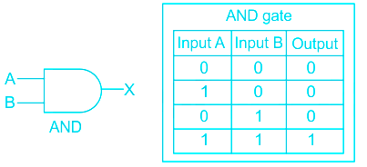
AND Gate: If both the inputs are high, it produces a high output.
- The Boolean algebra for AND gate is X = A. B
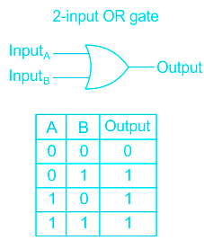
OR gate: If any of the input is high, it produces a high output.
- The Boolean algebra for OR gate is X = A + B
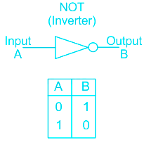
NOT gate: It inverts the input. Whatever the input is given, it changes its value at the output.
- The Boolean algebra for NOT gate is X = X̅
EXPLANATION:
- From the above table, it is clear that for a two-input AND gate, the output is “high” only when both the inputs are “high”. Therefore, option 1 is correct.
-
Question 43
5 / -1
Which of the following is the best choice for permanent magnets?
Solution
The permanent magnets are made from hard ferromagnetic materials (steel, cobalt steel, carbon steel etc). Since these materials have high retentivity, the magnet is quite strong. Due to their high coercivity, they are unlikely to be demagnetized by stray magnetic fields.
Permanent Magnets:
Permanent magnets are magnets with magnetic fields that do not dissipate under normal circumstances. They are made from hard ferromagnetic materials, which are resistant to becoming demagnetized.
Permanent magnets are made from a material that will inherit the properties of a strong magnetic field when exposed to it.
Properties:
Residual induction:
The residual induction is any magnetic induction that remains in a magnetic material after removal of an applied saturating magnetic field, measured in gauss or tesla. Residual induction is also known as magnetic remanence.
Coercivity:
- Coercivity (or the coercive field) is the property of a material to resist demagnetization due to the intensity of the material's magnetic field
- Coercivity is measured by the extent to which a demagnetizing field must be applied to reduce the material's magnetism to zero
- Permanent magnets are composed of materials with a high coercivity which retains their inherited magnetic fields under most conditions, unless intentionally demagnetized
Hysteresis loop:
- Wider hysteresis loops have high retentivity, coercivity, and saturation due to their larger hysteresis loop area
- These loops are typically found in hard magnetic materials
- Due to the size, these hysteresis loops have low initial permeability which leads to higher energy dissipation
- For these reasons, they are utilized in permanent magnets that have high resistance to demagnetization
- Demagnetization is more difficult to achieve in these wider hysteresis loops because there is a larger area to cover when reversing the hysteresis loop direction back to its original paramagnetic state
Note:
Diamagnetic materials
- Weak, negative susceptibility to magnetic fields
- Diamagnetic materials are slightly repelled by a magnetic field
- All the electrons are paired so there is no permanent net magnetic moment per atom
- Most elements in the periodic table, including copper, silver, and gold, are diamagnetic
Paramagnetic materials
- Small, positive susceptibility to magnetic fields
- These materials are slightly attracted by a magnetic field
- Paramagnetic properties are due to the presence of some unpaired electrons, and from the realignment of the electron paths caused by the external magnetic field
- Paramagnetic materials include magnesium, molybdenum, lithium, and tantalum
Ferromagnetic materials
- Have a large, positive susceptibility to an external magnetic field
- They exhibit a strong attraction to magnetic fields and can retain their magnetic properties after the external field has been removed
- Ferromagnetic materials have some unpaired electrons, so their atoms have a net magnetic moment
- Iron, nickel, and cobalt are examples of ferromagnetic materials.
-
Question 44
5 / -1
X-rays discovered by whom?
Solution
- Wilhelm Conrad Roentgen discovered X-Rays in 1895.
- He discovered while working with a cathode-ray tube in his laboratory.
- Frequency of X-Rays is 1016 to 1019 Hz.
- X-rays are used to detect the cracks in bones, in medicine and industries and also in security purposes.
-
Question 45
5 / -1
Which colour of light will have more resolving power for a telescope?
Solution
Concept:
- The reciprocal of the smallest angle subtended at the objective lens of a telescope by two-point objects which can be just distinguished as separate is called resolving power of a telescope.
- The white light is consists of seven colours – violet, indigo, blue, green, yellow, orange and red.
- The wavelength of red colour light is maximum among all the seven constituent colours and violet light is minimum.
The resolving power of a telescope is given by:
\(Resolving\;power\;\left( {R.P} \right) = \frac{D}{{1.22\;\lambda }}\)
Where D is the distance between two point object and λ is the wavelength of light used
Explanation:
- According to the above formula, the resolving power will be more for the light having a minimum wavelength.
- As the wavelength of the violet light is minimum. So resolving power for violet will be maximum. Hence option 3 is correct.
-
Question 46
5 / -1
Two masses of 1 kg and 4 kg have same Kinetic energy. What is the ratio of their momenta
Solution
CONCEPT:
- Kinetic energy (K.E): The energy possessed by a body by the virtue of its motion is called kinetic energy.
The expression for kinetic energy is given by:
\(KE = \frac{1}{2}m{v^2}\)
Where m = mass of the body and v = velocity of the body
- Momentum (p): The product of mass and velocity is called momentum.
Momentum (p) = mass (m) × velocity (v)
The relationship between the kinetic energy and Linear momentum is given by:
As we know,
\(KE = \frac{1}{2}m{v^2}\)
Divide numerator and denominator by m, we get
\(KE = \frac{1}{2}\frac{{{m^2}{v^2}}}{m} = \frac{1}{2}\frac{{\;{{\left( {mv} \right)}^2}}}{m} = \frac{1}{2}\frac{{{p^2}}}{m}\;\) [p = mv]
\(\therefore KE = \frac{1}{2}\frac{{{p^2}}}{m}\;\)
\(p = \sqrt {2mKE} \)
CALCULATION:
Given that:
K.E1 = K.E2= K.E (let say)
m1 = 1 kg and m2 = 4 kg
The relation between the momentum and the kinetic energy is given by:
\(P = \sqrt {2m\;K.E}\)
But as K.E is the same
∴ \(P \propto \sqrt m \)
Or, \(\frac{{{P_1}}}{{{P_2}}} = \sqrt {\frac{{{m_1}}}{{{m_2}}}} = \sqrt {\frac{{{1}}}{{{4}}}} =1: 2 \)
So option 1 is correct.
-
Question 47
5 / -1
The process in which the low frequency message signal is superimposed on a high frequency wave is called:
Solution
CONCEPT:
Attenuation:
- The loss of strength of a signal while propagating through a medium is known as attenuation.
Modulation:
- The original low-frequency message or information signal cannot be transmitted to long distances.
- Therefore, at the transmitter, the information contained in the low-frequency message signal is superimposed on a high-frequency wave, which acts as a carrier of the information.
- This process is known as modulation.
- There are several types of modulation, abbreviated as AM, FM, and PM.
Amplification:
- It is the process of increasing the amplitude (and consequently the strength) of a signal using an electronic circuit called the amplifier.
- Amplification is necessary to compensate for the attenuation of the signal in communication systems.
- The energy needed for additional signal strength is obtained from a DC power source.
- Amplification is done at a place between the source and the destination wherever signal strength becomes weaker than the required strength.
EXPLANATION:
- We know that the original low-frequency message or information signal cannot be transmitted to long distances.
- Therefore, at the transmitter, the information contained in the low-frequency message signal is superimposed on a high-frequency wave, which acts as a carrier of the information. This process is known as modulation. Hence, option 2 is correct.
-
Question 48
5 / -1
By which law, the direction of induced emf will be identified
Solution
Concept –
Lenz's Law –
- According to this law, the direction of induced emf or current in a circuit is such as to oppose the cause that produces it.
- This law gives the direction of induced emf/induced current.
- This law is based upon law of conservation of energy.
Faraday's Laws of Electromagnetic Induction –
- Whenever the number of magnetic lines of force (magnetic flux) passing through a circuit/coil changes an emf is produced in the circuit called induced emf.
- The induced emf persists only as long as there is change or cutting of flux.
- The induced emf is given by rate of change of magnetic flux linked with the circuit i.e.
\(e = - N\frac{{d{\rm{\Phi }}}}{{dt}}\)
Where e = induced emf, N = number of turns and Φ = magnetic flux
Negative sign indicates that induced emf (e) opposes the change of flux.
Fleming's right hand –
- This rule states that if we arrange the thumb, the centre finger, and the forefinger of the right hand at right angles to each other, so that the thumb points towards the direction of the magnetic force, the centre finger gives the direction of induced current and the forefinger points in the direction of magnetic field .
- Fleming's right-hand rule shows the direction of induced current.
Explanation –
- According to lenz’s law, the direction of induced emf or current in a circuit is such as to oppose the cause that produces it.
- Faraday's Laws of Electromagnetic Induction gives the magnitude of emf.
- Kirchhoff’s law is related to junction rule of current and loop rule of electrical circuit.
- Fleming's right-hand rule shows the direction of induced current but it gives no relation between the direction of induced emf or current in a circuit is such as to oppose the cause that produces it.
-
Question 49
5 / -1
In Huygens principle, the relation between wavefront and the ray of light is-
Solution
The correct answer is option 1) i.e. Ray of light is perpendicular to the wavefront.
CONCEPT:
- Huygens principle: It states that each point on a wavefront is a source of wavelets, which spread forward with the same speed.
- Wavefront: A wavefront is a surface or a line on which the disturbance at every point has the same phase.
- Wavelets: It is a wave-like oscillation with an amplitude that starts at zero, increases, and then decreases back to zero.
EXPLANATION:
- A wavefront is a locus of all the points in a wave that have the same phase.
- The wavefront forms consecutive concentric circles around the source of light.
- The rays show the direction of propagation of the wave.
- Therefore, the rays of light are always normal/perpendicular to the wavefront.
-
Question 50
5 / -1
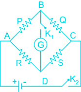
If P, Q, R and S represents resistances of 4 arms of the Wheatstone's bridge, then the sensitivity of Wheatstone's bridge will be maximum when
Solution
Concept:
- Wheatstone bridge: It is an arrangement of four resistance which can be used to measure one of them in terms of rest. Here arms AB and BC are called ratio arm and arms AC and BD are called conjugate arms.
- The bridge is said to be balanced when deflection in the galvanometer is zero i.e. no current flows through the galvanometer or in other words VB = VD.
- In the balanced condition
\(\frac{P}{Q} = \frac{S}{R}\)
- Under normal conditions, when the bridge is in the unbalanced condition the current flows through the galvanometer.
- When the bridge is in a balanced condition, there will be no current flow through the galvanometer.
- It is used for finding the value of unknown inductance, capacitance by making certain changes to the circuit.
The essential components are two known resistances, power supply, variable resistance, a galvanometer, and the unknown resistor.
It can be used along with other systems to measure physical parameters like strain, light, and temperature.
Explanation:
- In the balanced condition
\(\frac{P}{Q} = \frac{S}{R}\)
For maximum sensitivity of Wheatstone bridge:
- All four branch resistance of a Wheatstone bridge is the same.
P = Q = R = S.


 ×
×

 Sign in
 Profile
 Signout


