-
Question 1
5 / -1
Emission of an alpha particle leads to a:
Solution
CONCEPT:
- Radioactivity:
- Radioactive decay is the process by which an unstable atomic nucleus loses energy by radiation. A material containing unstable nuclei is considered radioactive.
- A radioactive nucleus consists of an unstable assembly of protons and neutrons which becomes more stable by emitting an alpha, a beta particle, or a gamma photon.
- Atoms are radioactive if their nuclei are unstable and spontaneously (and random) emit various particles α, β, and/or γ radiations.
- Three crucial forms of Radioactivity:
- Gamma Decay-(Photons having high energy are throw down).
- Beta Decay-(Discharge consists of Electrons).
- Alpha Decay-(Discharge consists of a Helium nucleus).
EXPLANATION:
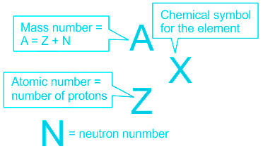
- An α particle is essentially a He nucleus consisting of two protons and two neutrons.
- Two protons correspond to 2 units of charge on an α particle.
- Two protons and two neutrons correspond to 4 units of mass of an α particle.
- Hence, the symbol for an α particle is 4He2.
- From the definition of α particle given above, emission of an α particle will lead to a decrease in 2 units of charge and a decrease in 4 units of mass of the atom.
- Hence, option 1 is correct.
 Additional Information
- The following table shows the list of particles with their respective features.
| Three forms of Radioactive Emissions |
| Characteristics | Alpha Particles | Beta Particles | Gamma rays |
| Symbols | α, 4He2 | β, 0e-1 | γ |
| Identity | Helium Nucleus | Electron | Electromagnetic radiation |
| Charge | +2 | -1 | None |
| Mass number | 4 | 0 | 0 |
| Penetrating power | Minimal(will not penetrate the skin) | Short(will penetrate skin & some tissue slightly) | Deep(will penetrate the tissue deeply) |
- When a Plutonium nucleus emits an α particle it losses 2 units of charge and 4 units of mass to give a Uranium nucleus.
239Pu94 → 235U92 + 4He2
-
Question 2
5 / -1
Optical communication using fibers is performed in the frequency range of:
Solution
CONCEPT:
The bandwidth of Transmission Medium:
- Similar to message signals, different types of transmission media offer different bandwidths.
- The commonly used transmission media are wire, free space, and fiber optic cable.
- Coaxial cable is a widely used wire medium, which offers a bandwidth of approximately 750 MHz.
- Such cables are normally operated below 18 GHz.
- Communication through free space using radio waves takes place over a very wide range of frequencies: from a few hundreds of kHz to a few GHz.
- This range of frequencies is further subdivided and allocated for various services as indicated in the given table.
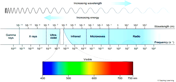
- Optical communication using fibers is performed in the frequency range of 1 THz to 1000 THz (microwaves to ultraviolet). An optical fiber can offer a transmission bandwidth in excess of 100 GHz.
- Spectrum allocations are arrived at by an international agreement. The International Telecommunication Union (ITU) administers the present system of frequency allocations.
| Service | Frequency bands | Comments |
| Standard AM broadcast | 540-1600 kHz | |
| FM broadcast | 88-108 MHz | |
| Television | 54-72 MHz 76-88 MHz 174-216 MHz 420-890 MHz | VHF (very high frequencies) TV UHF (ultra-high frequencies) TV |
| Cellular Mobile Radio | 896-901 MHz 840-935 MHz | Mobile to the base station Base station to mobile |
| Satellite Communication | 5.925-6.425 GHz 3.7-4.2 GHz | Uplink Downlink |
EXPLANATION:
- Optical communication using fibers is performed in the frequency range of 1 THz to 1000 THz (microwaves to ultraviolet). Hence, option 3 is correct.
-
Question 3
5 / -1
The number of electrons contained in 1 coulomb of charge is
Solution
Concept:
- Electric Current (I):
- It is defined as the net amount of electric charge that flows through a cross-section of a conductor in an electric circuit in a per unit time.
- S.I unit of electric current is Ampere(A).
- 1 Coulomb (C):
- One Coulomb of charge is equal to the charge transported by an electric current of constant magnitude in one second of time.
- It is defined as the product of a 6.24 × 10¹⁸ charge of an electron.
- It is the S.I unit of electric charge.
Charge of one electron = 1.6 × 10⁻¹⁹ Coulomb.
Explanation:
We know that e = 1.6 × 10⁻¹⁹ C,i.e charge on the electron.
The total charge required is 1 Coulomb, q = 1C
Therefore we also know that q = n × e, (n = number of electrons on the charge)
Hence, n = q/e....(1)
Substituting all the values in the equation (1)
n = 1/1.6 × 10-19 = 6.25 × 10¹⁸
So, if 1A current flows through the conductor then 6.25 × 10¹⁸ electrons flow per second across the cross section of the conductor.
-
Question 4
5 / -1
According to Huygens' principle secondary wavelets ___________.
Solution
CONCEPT:
Huygens' concepts of secondary wavelets:
- Huygen’s principle states that every point on the wavefront may be considered as a source of secondary spherical wavelets that spread out in the forward direction at the speed of light.
- The new wavefront is the tangential surface of all these secondary wavelets.
- Secondary sources start making their own wavelets, these waves are similar to that of the primary source.
EXPLANATION:
- Every point on the given wavefront acts as a source of a new disturbance called secondary wavelets which travel in all directions with the velocity of light in the medium.
- A surface touching these secondary wavelets tangentially in the forward direction at any instant gives the new wavefront at that instant. This is called a secondary wavefront.
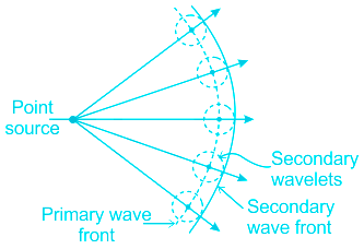
- From the above, it is clear that Huygens' concepts of secondary wavelets are a geometrical method to find a wavefront. Hence, option 3 is correct.
-
Question 5
5 / -1
The magnetic flux through a 50-turn coil increases at the rate of 0.05 Wb/s. What is the induced emf between the ends of the coil?
Solution
CONCEPT:
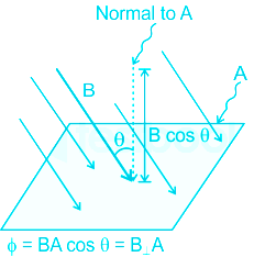
- Magnetic flux is total magnetic field that passes through the given area.
- If we choose a simple flat surface with area A and there is an angle θ between the normal to the surface and a magnetic field vector (magnitude B) then the magnetic flux is ϕ = BA cosθ
- Faraday's Law: Any change in the magnetic flux of wire will cause a voltage (induced emf) to be "induced" in the coil.
- This change can be produced by changing the magnetic field strength, moving the coil into or out of the magnetic field, moving a magnet toward or away from the coil,rotating the coil relative to the magnet, etc.
- Induced emf \(=-N \frac{\Delta \phi }{\Delta t}\)
CALCULATION:
Given that N=50 turns
\( \frac{\Delta \phi }{\Delta t}\)= 0.05 Wb/s
induced emf \(=-N \frac{\Delta \phi }{\Delta t}\)
= 50 × 0.05 = 2.5 Volt
So, The correct answer is Option 1, i.e 2.5 V

- Lenz's law says that the direction of the induced current in coil will be always in such a way as to oppose the change which produces the current.
- It is just a small addition to Faraday's law. See negative sign in the formula. Negative sign shows opposement.
-
Question 6
5 / -1
The resistance of the bulb filament is 100 Ω at a temperature of 100 °C, its temperature co-efficient of resistance be 0.005 per °C. its resistance will become 200 Ω at a temperature.
Solution
CONCEPT:
- The resistance of the conductor changes when the temperature of that conductor changes.
- New resistance is given by
⇒ Rt = R0(1 + αΔT)
Where Rt = the resistance of conductor after temperature changes
R0 = resistance of conductor before temperature changes
α = temperature coefficient
ΔT = final temperature – initial temperature
CALCULATION:
Given that,
Co-efficient of resistance (α) = 0.005 per °C
Let resistance of bulb filament be Ro at 0°C
Resistance of the bulb filament at 100° C (R) = 100Ω
- The change in temperature in the first case will be
⇒ ΔT = 100° C - 0° C = 100° C
⇒ Rt = R0(1 + αΔT)
⇒ 100 = R0(1 + 0.005 × 100)
⇒ 100 = 1.5 R0 -------- (1)
The temperature of the bulb filament at R = 200 Ω is T'
- Hence the resistance of bulb’s filament is given by
⇒ R’ = R (1 + α ΔT)
⇒ 200 = R0(1 + 0.005 × T') ------ (2)
On dividing equation 1 and 2, we get
\(⇒ \frac{100}{200} = \frac{1.5 R_0}{ R_0(1 + 0.005T')}\)
On solving above equation, we get
⇒ T’ = 400° C
-
Question 7
5 / -1
In a coil current changes from 2A to 4A in 0.05 second. If the average induced e.m.f. is 8 volt, then coefficient of self inductance is:
Solution
CONCEPT:
Self-Induction
- Whenever the electric current passing through a coil changes, the magnetic flux linked with it will also change.
- As a result of this, in accordance with Faraday’s laws of electromagnetic induction, an emf is induced in the coil which opposes the change that causes it.
- This phenomenon is called ‘self-induction’ and the emf induced is called back emf, current so produced in the coil is called induced current.
- Self-inductance of a solenoid is given by –
\(L=\frac{{{\mu }_{o}}{{N}^{2}}A}{l}\)
Where μo = Absolute permeability, N = Number of turns, l = length of the solenoid, the resistance of the coil (R) = 4Ω, and A = Area of the solenoid.
- Induced e.m.f can be given as
\(⇒ V_{l}=-L\frac{dI}{dt}\) -----(1)
Where
VL = induced voltage in volts
N = self-inductance of the coil
\(\frac{dI}{dt}=\) rate of change of current in ampere/second
CALCULATION:
Given I1 = 4A, I2 = 2A, dt = 0.05 sec, VL = 8 volt
⇒ dI = I2 - I1 = (2 - 4) = -2A
From equation 1,
\(\Rightarrow 8=-L\frac{(-2)}{0.05}\)
\(\Rightarrow L=0.2H\)
- Hence, option 1 is correct.
-
Question 8
5 / -1
The angular frequency of the charged particle in a cyclotron is
Solution
The correct answer is option 1) i.e. inversely proportional to its mass
CONCEPT:
- A cyclotron is a particle accelerator that accelerates charged particles to higher energies.
- The working principle of a cyclotron is the Lorentz force.
- The charged particle is placed at the center of the arrangement between the poles of two electromagnets.
- The magnetic field causes the particle to trace a circular path as it experiences a Lorentz force.
- An alternating voltage is applied across the setup, which further accelerates the particle.
- Lorentz force is the force experienced by electrically charged particles moving in a magnetic field.
- The magnitude of the magnetic force (F) on a charge (q) moving at a speed (v) in a magnetic field of strength B is given by
⇒ F = qvB
EXPLANATION:
- When a charged particle moves perpendicular to the magnetic field (θ = 90∘), it follows a curved path and undergoes circular motion.
- Here, the magnetic force supplies the centripetal force which keeps the particle in a circular motion.
- The centripetal force,
\(⇒ F_C = \frac{mv^2}{r}\)
Where m is the mass of the particle, v is the velocity of the particle, and r is the radius of the circular path traced by the particle.
\(\therefore F = F_C⇒qvB = \frac{mv^2}{r}\)
\(⇒\frac{v}{r} = \frac{qB}{m}\) ----(1)
- Angular velocity of the body is given as,
\(⇒ ω = \frac{v}{r} \)
Where r = radius and ω = 2πf, where f is the frequency.
Substituting (1) in the equation for ω,
\(\Rightarrow \omega = \frac{qB}{m} = 2\pi f\)
\(\Rightarrow f =\frac{qB}{2\pi m}\)
\(\Rightarrow f \propto \frac{1}{m}\)
- The angular frequency of the charged particle in a cyclotron is inversely proportional to its mass.
-
Question 9
5 / -1
Objects at different distances are seen by the eye. In this process which one of the following remains constant?
Solution
CONCEPT:
THE HUMAN EYE:
- The human eye is one of the most valuable and sensitive sense organs.
- It uses light and enables us to see the colourful world around us.
- The human eye is more or less like a photographic camera.
- The lens system of the eye forms an image of an object on a light-sensitive screen.
- The eyeball is almost spherical in shape having a diameter of about 23 cm.
EXPLANATION:
- Objects at different distances are seen by the eye by focusing them on the retina of the eye by changing the focal length of the eye lens.
- But the image is always formed at the retina and hence image distance from the eye lens remains constant. Therefore option 3 is correct.
Additional Information
EXTRA POINTS:
Different parts of the eyes and their functions are shown in the table:
Name of the Part | Characteristics | Function |
Cornea | The transparent spherical membrane covering the front part of the eye | Light enters the eye through this membrane; Most of the refraction happens here |
Eye Lens | transparent, biconvex structure in the eye | provides finer adjustment required to focus objects on the retina |
Iris | The dark muscular diaphragm between the cornea and the lens | controls the size of the pupil |
Pupil | An opening between the iris through which light enters the eye | regulates the amount of light entering the eye |
Ciliary Muscles | Attached to the eye lens |
hold the lens in position and modify the curvature of the lens.
|
Retina | the light-sensitive surface of an eye on which the image is formed | generate signals which are transmitted to the brain through optical nerves |
Optic Nerve | Attached to retina | transmits visual information from the retina to the brain |
-
Question 10
5 / -1
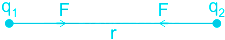
Two current carrying long wires are placed parallel to each other and separated by a distance d. If the force on the segment of the wires is F, then the force F is related to d as:
Solution
CONCEPT:
The force between two parallel currents:
- We know that there exists a magnetic field due to a conductor carrying a current.
- And an external magnetic field exerts a force on a current-carrying conductor.
- Therefore we can say that when two current-carrying conductors placed nearby each other will exert (magnetic) forces on each other.
- In the period 1820-25, Ampere studied the nature of this magnetic force and its dependence on the magnitude of the current, on the shape and size of the conductors, as well as, the distances between the conductors.
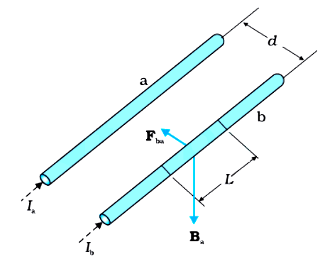
- Let two long parallel conductors a and b separated by a distance d and carrying (parallel) currents Ia and Ib respectively.
- The magnitude of the magnetic field intensity due to wire a, on the wire b is,
\(⇒ B_a=\frac{\mu_oI_a}{2\pi d}\)
- The magnitude of the magnetic field intensity due to wire b, on the wire a is,
\(⇒ B_b=\frac{\mu_oI_b}{2\pi d}\)
- The conductors 'a' and ‘b’ carrying a current Ia and Ib respectively will experience sideway forces due to magnetic field Bb and Ba respectively
EXPLANATION:
- If two current-carrying long wires A and B are placed parallel to each other and separated by a distance d. Then the force F on the segment L of the wires is given as,
\(\Rightarrow F=\frac{\mu_o I_aI_b}{2\pi d}L\) -----(1)
Where Ia = current in the wire A, Ib = current in the wire B, and d = distance between the wires
If Ia and Ib are constant, then,
\(\Rightarrow F\propto\frac{1}{d}\)
- Hence, option 3 is correct.
Additional Information
- The magnitude of the force on the segment L of the wire 'a' due to magnetic field Bb is given as,
\(⇒ F_{ab}=\frac{\mu_o I_aI_b}{2\pi d}L\)
- The magnitude of the force on the segment L of the wire 'b' due to magnetic field Ba is given as,
\(⇒ F_{ba}=\frac{\mu_o I_aI_b}{2\pi d}L\)
- The magnitude of the force per unit length on wire a and wire b is given as,
\(⇒ f_{ab}=f_{ba}=\frac{\mu_o I_aI_b}{2\pi d}\)
 Important Points
- When the current flows in the same direction in the two parallel wires then both wires attract each other and if the current flows in the opposite direction in the two parallel wires then both wires repel each other.
-
Question 11
5 / -1
When unpolarised light of intensity I is incident on a system of two polariser A followed by B, the intensity of emergent light is I/8. Find the angle between the polarisers A and B.
Solution
CONCEPT:
Malus law:
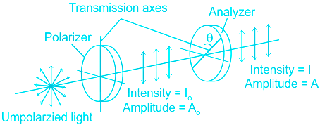
- Point 1: When Unpolarized light is incident on an ideal polarizer the intensity of the transmitted light is exactly half that of the incident unpolarized light no matter how the polarizing axis is oriented.
- Point 2: The intensity of plane-polarized light that passes through an analyzer varies as the square of the cosine of the angle between the plane of the polarizer and the transmission axes of the analyzer.
⇒ I = Io.cos2θ
Where I = intensity of incoming light and I = intensity light passing through Polaroid
CALCULATION:
Given I = intensity of an unpolarized beam of light, I2 = I/8, and θ = angle between the axes of the two polarisers
- We know that after the first polarisation of an unpolarized beam of light intensity becomes,
\(⇒ I_1=\frac{I}{2}\) -----(1)
- After the second polarisation intensity becomes,
⇒ I2 = I1.cos2θ
\(⇒ \frac{I}{8}=\frac{I}{2}cos^2θ\)
\(⇒ cos^2θ=\frac{1}{4}\)
\(⇒ cosθ=\frac{1}{2}\)
⇒ θ = 60°
- Hence, option 3 is correct.
-
Question 12
5 / -1
When a magnet is moved towards a coil, the induced e.m.f. in a coil is independent of the:
Solution
CONCEPT:
Faraday's first law of electromagnetic induction:
- Whenever a conductor is placed in a varying magnetic field, an electromotive force is induced.
- If the conductor circuit is closed, a current is induced which is called induced current.
Faraday's second law of electromagnetic induction:
- The induced emf in a coil is equal to the rate of change of flux linked with the coil.
\(\Rightarrow e=-N\frac{d\text{ }\!\!\Phi\!\!\text{ }}{dt}\)
Where N = number of turns, dΦ = change in magnetic flux and e = induced e.m.f.
- The negative sign says that it opposes the change in magnetic flux which is explained by Lenz law.
EXPLANATION:
- According to Faraday's second law of electromagnetic induction, the induced emf in a coil is equal to the rate of change of flux linked with the coil.
- The induced emf in a coil is given as,
\(\Rightarrow e=-N\frac{d\text{ }\!\!\Phi\!\!\text{ }}{dt}\) -----(1)
Where N = number of turns, dΦ = change in magnetic flux and e = induced e.m.f.
- By equation 1 it is clear that the induced emf in the coil depends on the change in flux, times, and the number of turns, but it is independent of the resistance of the coil.
- Hence, option 3 is correct.
-
Question 13
5 / -1
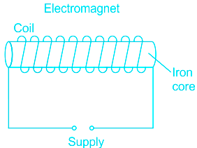
An electromagnet is
Solution
Concept:
Magnetic Effect of Current
A current-carrying conductor produces a magnetic field around us.
The magnetic force depends upon the magnitude of current and distance from the conductor.
This property of the current is used to make an electromagnet.
Electromagnet
- An electromagnet is a temporary magnet that should ideally have the property to behave as a magnet when current passes through it and lose magnetism as soon as the current is stopped.
- Soft iron is generally used for making electromagnets because it has high magnetic permeability, i.e. it can easily gain magnetic properties when current is passed around the core and quickly lose when the current is stopped.
- The soft iron inside the coil makes the magnetic field stronger because it becomes a magnet itself when the current is flowing
Explanation:
- So, an electromagnet behaves as magnet when switch is ON and loses magnetisam when switch is off.
- This makes electromagnet a temporary magnet.
So, the correct option is a temporary magnet.
-
Question 14
5 / -1
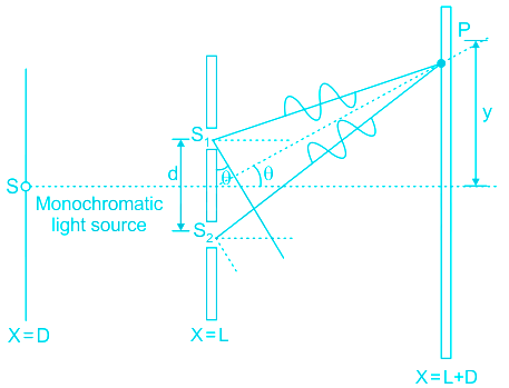
In a Young's double slit experiment, the intensity at the central maximum is I0. The intensity at a distance β/4 from the central maximum is (β is fringe width)
Solution
CONCEPT:
Young's double-slit experiment
- Young’s double-slit experiment helped in understanding the wave nature of light.
- The original Young’s double-slit experiment used diffracted light from a single monochromatic source of light.
- The light that comes from the monochromatic source is passed into two slits to be used as two coherent sources.
- At any point on the screen at a distance ‘y’ from the center, the waves travel distances l1 and l2 to create a path difference of Δl at that point.
- If there is a constructive interference on the point then the bright fringe occurs.
- If there is a destructive interference on the point then the dark fringe occurs.
Fringe width (β):
- The separation between any two consecutive bright or dark fringe is called fringe width.
- In Young’s double-slit experiment all fringes are of equal width.
- In Young’s double-slit experiment the fringe width is given as,
\(⇒ β=\frac{λ D}{d}\)
Where d = distance between slits, D = distance between slits and screen, and λ = wavelength
CALCULATION:
Given the Intensity of central maximum = Io, and y = \(\frac{\beta}{4}\)
Let the intensity of each source is I.
Then the intensity of central maxima is given as,
⇒ I0 = 4I -----(1)
- In Young’s double-slit experiment the fringe width is given as,
\(⇒ β=\frac{λ D}{d}\) -----(2)
We know that the path difference at a distance y from the central maxima is given as,
\(⇒ Δ x=\frac{yd}{D}\)
\(⇒ Δ x=\frac{\beta d}{4D}\) -----(3)
By equation 2 and equation 3,
\(⇒ Δ x=\frac{λ D}{d}\times\frac{ d}{4D}\)
\(⇒ Δ x=\frac{\lambda}{4}\) -----(4)
- The phase difference is given as,
\(⇒ Δϕ=\Delta x\left(\frac{2\pi}{\lambda}\right)\) -----(5)
By equation 4 and equation 5,
\(⇒ Δϕ=\frac{\lambda}{4}\times\left(\frac{2\pi}{\lambda}\right)\)
\(⇒ Δϕ=\frac{\pi}{2}\) -----(6)
We know that the intensity at a distance y is given as,
⇒ l' = 2l (1 + cos Δϕ) -----(7)
By equation 1 and equation 7,
\(⇒ I'=2\left(\frac{I_0}{4}\right)\left(1+cos\frac{\pi}{2}\right)\)
\(⇒ I'=\frac{I_0}{2}\)
- Hence, option 2 is correct.
-
Question 15
5 / -1
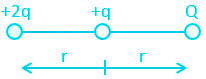
Three charges +2q, +q, and Q are placed as shown in the figure. For the net force on +q to be zero, the charge on Q must be
Solution
The correct answer is option 1) i.e. + 2q
CONCEPT:
- Coulomb's law: It states that the magnitude of the electrostatic force F between two point charges q1 and q2 is directly proportional to the product of the magnitudes of charges and inversely proportional to the square of the distance r between them.
It is represented mathematically by the equation:
\(F = \frac{kq_1 q_2}{r^2}\)
- Forces due to multiple charges: The force acting on a point charge due to multiple charges is the vector sum of all the individual forces acting on the charges.
CALCULATION:
Given that:
Let the three charges be q1 = + 2q, q2 = +q and q3 = Q
The net force acting on +q will be the sum of forces due to the charge q1 and that due to charge Q. Let these forces be F12 and F32.
Using Coulomb's law, \(F = \frac{kq_1 q_2}{r^2}\)
\(F_{12} = \frac{kq_1 q_2}{r^2} = \frac{k(2q) (q)}{r^2} \)
\(F_{32} = \frac{kq_3 q_2}{r^2} = \frac{k(Q) (q)}{r^2} \)
For the net force on +q to be zero, F12 + (-F32) = 0 ⇒ F12 = F32
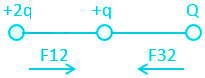
\(\frac{k(2q) (q)}{r^2} = \frac{k(Q) (q)}{r^2} \)
⇒ +2q = Q
-
Question 16
5 / -1
Which of the following statements is NOT true regarding the infrared radiation?
Solution
The correct answer is It is a longitudinal wave.
- Infrared radiation is a type of radiant energy that is invisible to human eyes. However, we can feel its heat.
- It is a part of the electromagnetic spectrum.
- In 1800, William Herschel conducted an experiment measuring the difference in temperature between the colours in the visible spectrum. He discovered infrared light in this experiment.
- Infrared waves are between 700 nm (nanometers) and 1 mm.
- Electromagnetic waves are waves that are created as a result of vibrations between an electric field and a magnetic field. These waves do not require a medium to propagate.
- The electromagnetic spectrum from longest wavelength to shortest - Radio waves, Microwaves, Infrared, Visible, Ultraviolet, X-rays, and Gamma-rays. The frequency increases from radio waves to gamma-rays.
- The Transverse waves are waves where the oscillations are perpendicular to the direction of the wave or path of propagation.
- The longitudinal waves are waves where the vibrations are parallel to the direction of propagation.
- Infrared waves are transverse waves in nature.
-
Question 17
5 / -1
Out of the following particles moving with the same velocity, _________ has the longest wavelength.
Solution
Concept:
Matter waves:
The light is a wave having particle nature. In a similar way, we say that the matter moving at a certain speed is having wave-like characteristics.
The wavelength of such wave is called de Broglie wavelength.
- de Broglie wavelength associated with the particle is given as
\( \lambda = \frac{h}{p} = \frac{h}{mv}\) -----(1)
h is Planck's constant, p is momentum.
α particle:
- Alpha rays are positively charged particles.
- An α particle is essentially a He nucleus consisting of two protons and two neutrons.
- Two protons correspond to 2 units of positive charge on an α particle.
- Two protons and two neutrons correspond to 4 units of mass of an α particle.
- The symbol for an α particle is 4He2.
β particle:
- β particles are high-speed electron or its positive counter part positron emitted by the radioactive decay.
- There are two types of β particle, β− (electron) and β+ (positron) having mass same as an electron.
Explanation:
From de Broglie equation we have
\( \lambda = \frac{h}{p} = \frac{h}{mv}\)
\(\implies \lambda \propto \frac{1}{m}\)
h is constant and it is given velocity v is also constant.
So, the particle with minimum mass will have a maximum wavelength.
β particle has mass same as an electron which is having a much lower mass than proton or neutron.
So, the correct option is β - particle
-
Question 18
5 / -1
A thin double convex lens has radii of curvature each of magnitude 40 cm and is made of glass with refractive index 1·5. The focal length of the lens is:
Solution
CONCEPT:
Lens Maker's Formula:
- If R1 and R2 are the radii of curvature of first and second refracting surfaces of a thin lens of focal length f and refractive index μ (w.r.t. surrounding medium) then the relation between f, μ, R1 and R2 are known as lens maker’s formula.
\(\frac{1}{f} = \left( {μ - 1} \right)\left( {\frac{1}{{{R_1}}} - \frac{1}{{{R_2}}}} \right)\)
CALCULATION:
Give - Refractive index of glass (μ) =1.5 and R1 = 40 cm and R2 = -40 cm
- The focal length of the lens is
\(⇒ \frac{1}{f} = \left( {μ - 1} \right)\left( {\frac{1}{{{R_1}}} - \frac{1}{{{R_2}}}} \right)\)
\(⇒ \frac{1}{f} = \left( {1.5 - 1} \right)\left( {\frac{1}{{{40}}} - \frac{1}{{{(-40)}}}} \right)=0.5(\frac{2}{40})=0.025\, cm\)
⇒ f = 40 cm
-
Question 19
5 / -1
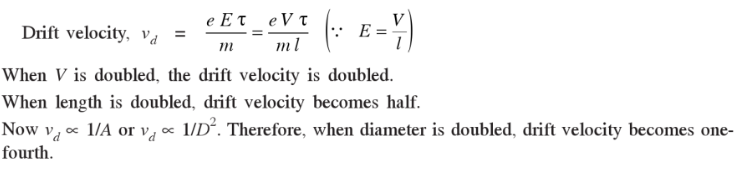
A potential difference 'V' is applied across a conducting wire of diameter 'd' and length 'L'. When the diameter is doubled, the drift velocity-
Solution
The correct answer is option 1) i.e. becomes (1/4)th of the initial value
CONCEPT:
- Drift velocity: The average velocity attained by the electrons under the influence of an electric field is termed the drift velocity.
- The free electrons are always in a constant random motion in the conductor.
- When the conductor is connected to a battery, an electric field is generated.
- When these free electrons are subjected to an electric field, they slowly drift in the direction of the electric field applied, while maintaining the random motion.
- At this point, the net velocity of the electrons is called its drift velocity.
The drift velocity (vd) of the electron in a conductor is given by:
\(v_d =\frac{I}{nAq}\)
Where I is the current flowing through the conductor, A is the area of cross-section of the conductor, q is the charge on the electron and n is the number of electrons.
EXPLANATION:
We know that, \(v_d =\frac{I}{nAq}\)
A = πd2/4
So vd ∝ 1/d2
- If the diameter is doubled then the drift velocity becomes (1/4)th of the initial value.
-
Question 20
5 / -1
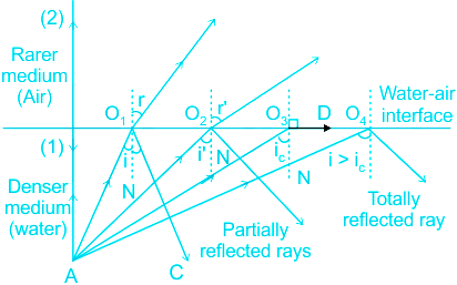
Total internal reflection is possible when light travels from
Solution
Concept:
Total Internal Reflection (TIR):
- When a ray of light goes from denser to the rarer medium it bends away from the normal and as the angle of incidence in denser medium increases, the angle of refraction in the rarer medium also increases and at a certain angle, the angle of refraction becomes 90°, this angle of incidence is called critical angle (C).
- When the Angle of incidence exceeds the critical angle then light ray comes back into the same medium after reflection from the interface.
- This phenomenon is called Total internal reflection (TIR).
Explanation:
- TIR happens when a ray of light travels from an optically denser medium to a rarer medium.
- Glass is optically denser than water.
- The speed of light in glass is less than that of water.
- When light travels from glass to water, TIR may happen.
- Glass to water is the correct option.
Considering other options
- Air to water: It is not possible as air is optically rarer than water.
- Air to glass: air is optically rarer than glass.
- Water to glass: water is optically rarer than glass.
Additional Information
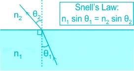
Snell's law:
- The ratio of the sine of the angle of incidence to the sine of the angle of refraction is a constant, for the light of a given colour and for the given pair of media.
\(⇒ \frac{sin\, i}{sin\, r}=Constant\)
Where I = angle of incidence and r = angle of refraction
Refractive index:
- When light travels from medium 1 to medium 2, then the ratio of the speed of light in medium 2 to the speed of light in medium 1 is called the refractive index of medium 1 with respect to medium 2.
\(⇒ μ_{12}=\frac{v_2}{v_1}\)
- If medium 1 is denser compared to medium 2, then the refractive index of medium 1 with respect to medium 2 will be greater than 1.
- If medium 1 is rarer compared to medium 2, then the refractive index of medium 1 with respect to medium 2 will be less than 1.
-
Question 21
5 / -1
The intrinsic semiconductor becomes an insulator at:
Solution
CONCEPT:
Semiconductor:
- Semiconductors are the materials that have a conductivity between conductors and insulators.
- Semiconductors are made of compounds such as gallium arsenide or pure elements, such as germanium or silicon.
- Holes and electrons are the types of charge carriers accountable for the flow of current in semiconductors.
- Holes (valence electrons) are the positively charged electric charge carrier whereas electrons are the negatively charged particles.
EXPLANATION:
- The resistance of semiconductor materials decreases with the increase in temperature and vice-versa.
- At absolute zero Kelvin temperature, the covalent bonds are very strong, and there are no free electrons, and the semiconductor behaves as a perfect insulator.
- Hence, option 4 is correct.
-
Question 22
5 / -1
Which one of the following sets of properties are relevant for an electrical fuse wire needed for normal applications?
Solution
The correct option is 4.
CONCEPT:
- Fuse: A fuse is an electrical safety device that operates to provide overcurrent protection of an electrical circuit.
- Properties of fuse:
- High resistance: The resistance of the fuse must have high so that it can carry a short circuit current when a fault occurs.
- Low melting point: The meting point of fuse wire should be low so that it can melt immediately when excess current flows through it.
- It is used in a series of equipment as a safety device.
- The material used for making a fuse wire is an alloy of lead and tin.
Working of fuse:
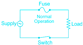
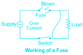
EXPLANATION:
- The resistance of the fuse must be high so that it can carry a short circuit current when a fault occurs.
- Resistance is directly proportional to the length of the wire. If resistance is high then the length is also large.
- Resistance of thin wire is more than that of a thick wire of the same length because resistance is inversely proportional to the area of cross-section and the thin wire has less area of cross-section, therefore, higher resistance.
- Hence, for a normal application, an electrical fuse wire needs a large length, thin wire, and low melting point.
-
Question 23
5 / -1
A typical cell develops a voltage of 0.5-1 V and can produce about ______ of electricity when exposed to the Sun.
Solution
Concept:
Solar cell: A solar cell, or photovoltaic cell, is an electrical device that converts the energy of light (Sunlight) directly into electricity by the photovoltaic effect, which is a physical and chemical phenomenon.
- Solar cells are made of semiconductor materials like silicon, cadmium telluride, and copper indium gallium selenide.
- The working principle of solar cells is based on the photovoltaic effect.
- The photovoltaic effect is the production of electricity by a material when it is exposed to light.
- The common single-junction silicon solar cell can produce a maximum open-circuit voltage of approximately 0.5 - 0.6 V and produce 0.7 W on exposure to the Sun.
- For making the solar cell, semiconductor materials are used such that silicon, cadmium telluride, and copper indium gallium selenide.
- Copper, Iron, and Aluminium are conductors and metals they are used to make wires and various metallic object.
Additional Information
Solar Cell:
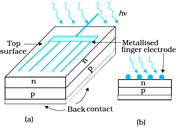
- A solar cell is basically a p-n junction that generates emf when solar radiation falls on the p-n junction.
- It works on the same principle (photovoltaic effect) as the photodiode, except that no external bias is applied and the junction area is kept much larger for solar radiation to be incident because we are interested in more power.
- A p-Si wafer of about 300 μm is taken over which a thin layer (~0.3 μm) of n-Si is grown on one side by the diffusion process.
- The other side of p-Si is coated with a metal (back contact). On the top of the n-Si layer, a metal finger electrode (or metallic grid) is deposited. This acts as a front contact.
- The metallic grid occupies only a very small fraction of the cell area (< 15%) so that light can be incident on the cell from the top.
- The generation of emf by a solar cell, when light falls on, it is due to the following three basic processes: generation, separation, and collection:
- Generation of e-h pairs due to light (with hν > Eg) close to the junction.
- Separation of electrons and holes due to electric field of the depletion region. Electrons are swept to n-side and holes to p-side.
- The electrons reaching the n-side are collected by the front contact and holes reaching the p-side are collected by the back contact.
- Thus p-side becomes positive and the n-side becomes negative giving rise to photovoltage.
- When an external load is connected a photocurrent flows through the load.
-
Question 24
5 / -1
Which among the following is an electromagnetic wave ?
Solution
Concept:
Electric Field
- The electric force per unit positive charge at a given point is called an electric field.
- A charge kept static, or in constant motion or accelerated produces an electric field around it which changes with time.
Magnetic Field
- A magnetic field is the measure of magnetic force at a particular point.
- A magnetic field is produced by a current-carrying wire which contains charges in motion.
- So, basically, a charge in constant motion produces a magnetic field around it.
- When the charge is accelerated the magnetic field varies with time.
Electromagnetic Wave
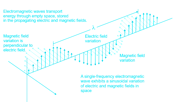
- Electromagnetic waves are composed of oscillating magnetic and electric fields.
- The electric field and magnetic field of an electromagnetic wave are perpendicular to each other.
- These waves do not require a medium to travel. EM waves travel at a constant velocity of 3 x 10⁸ m/s in a vacuum.
Alpha Beta and Gamma rays
Radioactive decay:
- When n/p ratio (n is a number of neutrons, p is the number of protons) of an atomic nucleus is high enough to make it unstable, resulting in radioactive decays.
- Radioactive decay mainly emits α- particles, β- particles, and gamma rays.
β-decay:
- It is a type of radioactive decay in which a proton is transformed into a neutron or vice versa inside the nucleus of the radioactive sample.
- Beta-decay occurs when, in a nucleus with too many protons or too many neutrons, one of the protons or neutrons is transformed into the other.
- This is a particle and not a wave
Gamma Rays:
- Gamma decay is the emission of energy in the form of electromagnetic waves from the nucleus of the atom.
- Gamma Rays do not have rest mass just as any electromagnetic waves.
Alpha Particles:
- ( 2α 4 ) Alpha particles are particles with the number of protons (atomic number) 2 and the number of neutron and proton (mass number) 4. It is similar to Helium Atom.
- It is obtained from the radioactive decay process of a heavy nucleus.
- It is particle and not a wave.
Ultrasonic waves
- The ultrasonic waves are mechanical waves and do not lie in the category of electromagnetic waves.
- These are waves like sound waves having a frequency of more than 20,000 Hz.
- These are not audible to normal human eyes.
Explanation:
The following things can be concluded.
- α and β rays are particles and not wave.
- γ is an electromagnetic wave.
- Ultrasonic waves are mechanical waves.
So, the only electromagnetic wave is γ.
-
Question 25
5 / -1
Which of the following is not correct about the Biot-Savart’s law?
Solution
CONCEPT:
- Biot-Savart's Law: Biot-Savart’s law is used to determine the magnetic field at any point due to a current-carrying conductor.
- This law is although for infinitesimally small conductor yet it can be used for long conductors.
EXPLANATION:
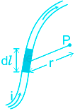
According to Biot-Savart Law, the magnitude of the magnetic field at point ‘ P ’ is
- directly proportional to the current through the conductor i.e. dB ∝ I
- directly proportional to the length of the current element i.e. dB ∝ dl
- directly proportional to sinθ
- inversely proportional to the square of the distance from the current element i.e. dB ∝ 1/r2
Combining all these four factors, we get
\(dB \propto \frac{{idl\sin \theta }}{{{r^2}}}\)
Or,
\(dB = k\frac{{idl\sin \theta }}{{{r^2}}}\)
Where the proportionality constant K depends on the medium between the observation point P and the current element and the system chosen. For free space and SI units,
\(dB = \frac{{{\mu _o}}}{{4\pi }}\frac{{idl\sin \theta }}{{{r^2}}}\)
Where μo = Absolute permeability of air or vacuum, \(i\overrightarrow {dl} \) = Current element and r = distance.
-
Question 26
5 / -1
A charge of magnitude Q is placed at a distance \(\dfrac{R}{3}\) from the center of a spherical shell of radius R, uniformly charged to the charge density σ. The electrostatic force on Q is:
Solution
Ans: Option 4)
CONCEPT:
- Gauss theorem: This theorem states that the surface integral of the normal component of the electric intensity E over a closed surface is always equal to \(\frac{1}{ϵ _{0}}\) times the total charge Q inside it.
\(E\times area= \frac{Q}{ϵ _{0}}\)
Where Q is the charge, ϵ0 is the permittivity of free space.
EXPLANATION:
- Here the charge is laying inside the shell and having a radius R/3 smaller than the spherical shell radius R.
- So as per Gauss' law, the electric field intensity is zero due to the charge enclosed by such a surface is zero because the charge density is at the surface of the sphere.
- Therefore the net force is zero on the given charge.
- correct option is 4).
-
Question 27
5 / -1
Electric field strength due to a dipole of moment p at a distant point r along the axis of the dipole is:
Solution
The correct answer is option 1) i.e. \(E=\dfrac{1}{2\pi\epsilon_0} \dfrac{p}{r^3}\)
CONCEPT:
- Electric field strength is a measure of the electric field intensity at a point due to a charge. It is the amount of electric force produced per unit charge.
- Electric field strength (E) at a point due to a point charge q is given by the formula
E = \(\frac{q}{4\pi \epsilon_0 r^2}\)
Where r is the distance from the point charge to the point at which E is determined.
- Electric dipole a couple formed from two equal opposite charges q and –q, which are separated by a distance 2a.
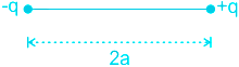
- Electric dipole moment p due to an electric dipole is given by
p = 2a × q
CALCULATION:
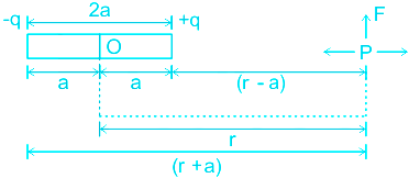
Let us consider a point x at a distance of r from the centre of an electric dipole, along its axis.
Electric dipole moment, p = 2aq
The electric field strength at point x due to -q, E1 = \(\frac{-q}{4\pi \epsilon_0 (r+a)^2}\)
The electric field strength at point x due to +q, E2 = \(\frac{+q}{4\pi \epsilon_0 (r-a)^2}\)
The net electric field at point x, E = E1 + E2 = \(\frac{-q}{4\pi \epsilon_0 (r+a)^2}\) + \(\frac{+q}{4\pi \epsilon_0 (r-a)^2}\)
⇒ \(\frac{q}{4\pi \epsilon_0} [\frac{1}{(r-a)^2} - \frac{1}{(r+a)^2} ]\) = \(\frac{q}{4\pi \epsilon_0} [\frac{(r+a)^2 -(r-a)^2 }{(r^2-a^2)^2} ] = \frac{q}{4\pi \epsilon_0}[\frac{4ar}{(r^2-a^2)^2}]\)
⇒ E = \(\frac{1}{4\pi \epsilon_0 } \frac{4aqr}{(r^2-a^2)^2}\)
Let us assume that the point x is at distance very far i.e. r >> a. Hence, we can safely neglect a2.
∴ E = \(\frac{1}{4\pi \epsilon_0 } \frac{4aqr}{(r^2)^2} = \frac{1}{4\pi \epsilon_0 } \frac{2(2aq)r}{r^4} = \frac{1}{4\pi \epsilon_0 }\frac{2(p)}{r^3} \) (∵ p = 2aq)
⇒ E = \( \frac{1}{2\pi \epsilon_0 }\frac{p}{r^3} \)
-
Question 28
5 / -1
The masses of two particles having same kinetic energy are in the ratio of 2 ∶ 1. Their de Broglie wavelengths are in the ratio
Solution
Concept:
The de-Broglie wavelength is given by:
\(\lambda = \frac{h}{{mv}} = \frac{h}{p}\)
m is the mass of the particle
h is the plank's constant
v is the velocity of the particle
p = momentum.
As can be seen from the relation "The de-Broglie wavelength is inversely proportional to the mass of the particle and its velocity but is independent of the nature of the particle."
\(\Rightarrow p = \frac{h}{\lambda }\)
The Kinetic energy in terms of momentum is given as:
\(K.E.\; = \frac{{{p^2}}}{{2m}}\)
Using the expression of momentum (p) in K.E.
\(K.E. = \frac{{{h^2}}}{{2m\;{\lambda ^2}}}\)
Calculation:
Given,
K.E. (1st object) = K.E. (2nd Object)
The ratio of their masses = \(\frac{{{m_1}}}{{{m_2}}} = \frac{2}{1}\)
We know that,
\(K.E. = \frac{{{h^2}}}{{2m\;{\lambda ^2}}}\)
\( \Rightarrow {\lambda ^2} = \frac{{{h^2}}}{{2m\;\left( {K.E} \right)}}\)
Since (K.E)1 = (K.E)2
\(\frac{{{{\left( {{\lambda _1}} \right)}^2}}}{{{{\left( {{\lambda _2}} \right)}^2}}} = \frac{{\left( {\frac{{{h^2}}}{{2{m_1}\;{{\left( {K.E} \right)}_1}}}} \right)}}{{\left( {\frac{{{h^2}}}{{2{m_2}\;{{\left( {K.E} \right)}_2}}}} \right)}} = \frac{{{m_2}}}{{{m_1}}} = \frac{1}{2}\)
\(\frac{{{\lambda _1}}}{{{\lambda _2}}} = \sqrt {\frac{1}{2}} = \frac{1}{{\sqrt 2 }}\)
-
Question 29
5 / -1
If the permittivity of the medium is ϵ then the dielectric constant of the medium is:
Solution
CONCEPT:
Dielectric:
- A dielectric is a material that has poor electrical conductivity but inherits an ability to store an electrical charge(due to Dielectric polarization).
Dielectric constant (K):
- It is defined as the ratio of the permittivity of the substance ϵ to the permittivity of the free space ϵo.
\(\Rightarrow K=\frac{ϵ}{ϵ_o}\)
- For vacuum K = 1.
- The dielectric constant is a dimensionless quantity.
- For any dielectric substance, the K is always greater than 1.
EXPLANATION:
- The dielectric constant is defined as the ratio of the permittivity of the substance ϵ to the permittivity of the free space ϵo.
\(\Rightarrow K=\frac{ϵ}{ϵ_o}\)
- Hence, option 2 is correct.
-
Question 30
5 / -1
A horizontal metal wire is carrying an electric current from the north to the south. Using a uniform magnetic field, it is to be prevented from falling under gravity. The direction of this magnetic field should be towards the_______
Solution
CONCEPT:
- Magnetic force on a current-carrying conductor placed in a field is given by
\(F = I (\vec{L}\times \vec{B})\)
where i is the current in the conductor, L is the length of the conductor, B is the magnetic field in which the conductor is placed.
- The direction of this magnetic force can be found using vector formula.
EXPLANATION:
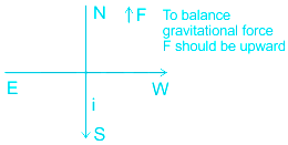
- A horizontal metal wire is carrying electric current from the north to the south. (As given in the figure)
- By using a uniform magnetic field, we will prevent it from falling under gravity.
- For this, the magnetic force on the wire should be in an upward direction.
\(F = I (\vec{L}\times \vec{B})\)
- The direction of F should be upward to balance the gravitational force, L is the direction of the current. So by vector cross product direction, to get F in the upward direction, B should in the east direction.
- So, The direction of this magnetic field should be towards the east. Hence the correct answer is option 1.
-
Question 31
5 / -1
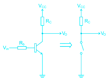
When the transistor is used in the cut-off or saturation state, it acts as?
Solution
CONCEPT:
TRANSISTOR:
- An electronic device made using semiconductor material like Si, Ge, As etc.
- Transistors are used to amplify the electronic signals
- Transistor can be also operated as a switch in a certain condition
TRANSFER CHARACTERISTICS :
- These characteristics show the behaviour of an electronic device.
- Transfercharctersitics can be drawn between input and output variables.
- Output Voltage transfer characteristic is plotted V0 against Vi
- A transistor can be used as a switch in the cutoff region
EXPLANATION:
- When a transistor works as a switch it works in cut-off and saturation regions.
- In the cut-off state, both emitter-base junction and the collector-base junctions are reverse biased.
- But in the saturation region, both the junctions are forward biased.
This is explained with the help of the following circuit diagram:
-
Question 32
5 / -1
The electric field intensity at a point due to point charge of 25 × 10-3 µC is 100 N/C. Calculate the electric potential at that point.
Solution
CONCEPT:
Electric potential (V):
- The potential difference between two points in an electric field may be defined as the amount of work done in moving a unit positive charge from one point to the other against the electrostatic force i.e.,
\({\rm{Electric\;potential\;}}\left( {\rm{V}} \right) = \frac{{{\rm{Work\;done\;}}\left( {\rm{W}} \right)}}{{{\rm{Charge\;}}\left( {\rm{q}} \right)}}\)
- The electric potential V at a point P due to point charge +q at a distance r is given by
\(V=\frac{1}{{4{\rm{\Pi }}\varepsilon_o }}\frac{q}{r}\) ---------- (1)
CALCULATION:
Given - q = 25 × 10-3 µC = 25 × 10-9 C and E = 100 N/C
We know that the electric field intensity (E) a point due to point charge +q at a distance r is given by
\(\Rightarrow E=\frac{1}{{4{\rm{\Pi }}\varepsilon_o }}\frac{q}{{{r^2}}}\)
\(\Rightarrow 100=\frac{1}{{4{\rm{\Pi }}\varepsilon_o }}\frac{q}{{{r^2}}}\)
\(\Rightarrow 100 =\frac{1}{{4{\rm{\Pi }}\varepsilon_o }}\frac{{25\;\times\;{{10}^{ - 9}}}}{{{r^2}}}\)
\(\Rightarrow {r^2} = \frac{1}{{4{\rm{\Pi }}\varepsilon_o }}\frac{{25\;\times\;{{10}^{ - 9}}}}{{100}}\)
\(\Rightarrow {r^2} = \frac{1}{{4{\rm{\Pi }}\varepsilon_o }}\frac{{{{10}^{ - 9}}}}{4}\)
\( \Rightarrow {r^2} = 9 \times {10^9} \times \frac{{{{10}^{ - 9}}}}{4} = \frac{9}{4} = \frac{3}{2}\)
Knowing the value of r, the electric potential can be computed using Equation 1
\(V=\frac{1}{{4{\rm{\Pi }}\varepsilon_o }}\frac{q}{r}\)
\(V = \frac{1}{{4{\rm{\Pi }}\varepsilon_o }}\frac{{25\;\times\;{{10}^{ - 9}}}}{{3/2}}\)
\( \Rightarrow V = 9 \times {10^9} \times \frac{{25 \times {{10}^{ - 9}}}}{{\frac{3}{2}}} = 150\;V\)
-
Question 33
5 / -1
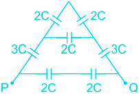
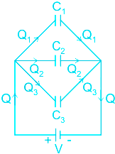
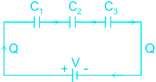
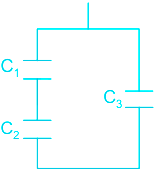
Find the equivalent capacitance between PQ:
Solution
CONCEPT:
Capacitor:
- The capacitor is a device in which electrical energy can be stored.
- In a capacitor, two conducting plates are connected parallel to each other and separated by an insulating medium carrying charges of equal magnitudes and opposite signs.
- The space between the two plates can either be a vacuum or an electric insulator such as glass, paper, air, or a semi-conductor called a dielectric.
1. Capacitors in series
- When two or more capacitors are connected one after another such that the same charge gets generated on all of them, then it is called capacitors in series.
- The net capacitance/equivalent capacitance (C) of capacitors in series is given by,
\(⇒\frac{1}{C} = \frac{1}{{{C_1}}} + \frac{1}{{{C_2}}}+...+ \frac{1}{{{C_n}}}\)
2. Capacitors in parallel
- When the plates of two or more capacitors are connected at the same two points and the potential difference across them is equal, then it is called capacitors in parallel.
- The net capacitance/equivalent capacitance (C) of capacitors in parallel is given by,
\(⇒ C = C_1+ C_2+...+ C_n\)
CALCULATION:
The given diagram is,
-----(1)
Figure 1 can be drawn as,
 -----(2)
In figure 2 the equivalent capacitance in the upper branch of RS is given as,
\(⇒\frac{1}{C_1} = \frac{1}{{{2C}}} + \frac{1}{{{2C}}}\)
⇒ C1 = C
So the equivalent capacitance between RS is given as,
⇒ CRS = C1 + 2C
⇒ CRS = C + 2C
⇒ CRS = 3C
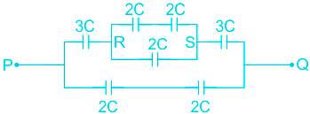
The figure 2 can be drawn as,
 -----(3)
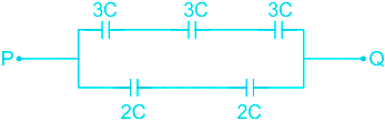
From figure 3 the equivalent capacitance in the upper branch of PQ is given as,
\(⇒\frac{1}{C_{2}} = \frac{1}{{{3C}}}+\frac{1}{{{3C}}}+\frac{1}{{{3C}}}\)
⇒ C2 = C
From figure 3 the equivalent capacitance in the lower branch of PQ is given as,
\(⇒\frac{1}{C_{3}} = \frac{1}{{{2C}}}+\frac{1}{{{2C}}}\)
⇒ C3 = C
So the equivalent capacitance between PQ is given as,
⇒ CPQ = C2 + C3
⇒ CPQ = C + C
⇒ CPQ = 2C
- Hence, option 1 is correct.
-
Question 34
5 / -1
Which of the following process is used for the retrieval of information from the carrier wave at the receiver?
Solution
CONCEPT:
Attenuation:
- The loss of strength of a signal while propagating through a medium is known as attenuation.
Modulation:
- The original low-frequency message or information signal cannot be transmitted to long distances.
- Therefore, at the transmitter, the information contained in the low-frequency message signal is superimposed on a high-frequency wave, which acts as a carrier of the information.
- This process is known as modulation.
- There are several types of modulation, abbreviated as AM, FM, and PM.
Demodulation:
- The process of retrieval of information from the carrier wave at the receiver is termed demodulation.
- This is the reverse process of modulation.
EXPLANATION:
- The process of retrieval of information from the carrier wave at the receiver is termed demodulation. Hence, option 2 is correct.
-
Question 35
5 / -1
The wavelength of the incident photons for a photoelectric emission process is increased then the photoelectric current will-
Solution
CONCEPT:
- Photoelectric effect: When light of sufficiently small wavelength is incident on a metal surface, electrons are ejected from the metal instantly. This phenomenon is called the photoelectric effect.
- Photocurrent: The rate of flow of electrons in the photoelectric emission process is called photocurrent.
- The photocurrent depends on the intensity of the incident photons.
- Stopping potential: The photocurrent may be stopped by applying a negative potential to anode w.r.t. cathode. The minimum potential required to stop the electron emitted from metal so that its kinetic energy becomes zero.
- Work function: It is the minimum amount of energy required so that metal emits an electron. It is represented with ϕ. Its unit is eV or joules.
- It has different values for different metals.
Einstein’s equation for the photoelectric effect is given by:
h ν = ϕ + K.E
Where h = planks constant = 6.6 × 10-34 = 4.14 × 10⁻¹⁵ eV-s, ν = incident frequency, ϕ = work function
EXPLANATION:
- Photocurrent depends on the intensity of the incident photons. It is independent of the wavelength of the incident photons. So there will be no effect on photocurrent by changing the wavelength of the incident photons. So option 3 is correct.
-
Question 36
5 / -1
Three similar capacitors of capacitance 4 μF each are connected together in which of the following manner that the equivalent capacitance is equal to 6 μ F?
Solution
CONCEPT:
Combination of capacitors:
| Parallel combination | Series combination |
| When two or more capacitors are connected in such a way that their ends are connected at the same two points and have an equal potential difference for all capacitor is called a parallel combination of the capacitor. | When two or more capacitors are connected end to end and have the same electric charge on each is called the series combination of the capacitor. |
 |  |
Equivalent capacitance (Ceq) for parallel combination: Ceq = C1 + C2 + C3 | Equivalent capacitance (Ceq) in series combination: \(\frac{1}{{{C_{eq}}}} = \frac{1}{{{C_1}}} + \frac{1}{{{C_2}}} + \frac{1}{{{C_3}}}\) |
Where C1 is the capacitance of the first capacitor, C2 is the capacitance of the second capacitor and C3 is the capacitance of the third capacitor
CALCULATION:
Given C1 = C2 = C3 = C = 4 μF and Ceq = 6 μF
When capacitors are connected in parallel:
⇒ Ceq = C + C + C = 4 + 4 + 4 = 12 μF
- When capacitors are connected in series:
\(\Rightarrow \frac{1}{C_{res}}=\frac{1}{C}+\frac{1}{C}+\frac{1}{C}\)
\(\Rightarrow C_{res}=\frac{C}{3}\) = 4/3 = 1.33 μF
- When two capacitors are connected in series with the third capacitor in parallel:
- Resultant of the series arrangement,
\(\Rightarrow \frac{1}{C_{s}}=\frac{1}{C}+\frac{1}{C}\)
\(\Rightarrow C_{s}=\frac{C}{2}\)
Equivalent capacitance is given by:
\(\Rightarrow C_{eq}=\frac{C}{2}+C\) = 1.5 C = 1.5 × 4 = 6 μF
- Thus two of the capacitors will be in series and one of them will be in parallel with them.
- Hence option 4 is correct.
-
Question 37
5 / -1
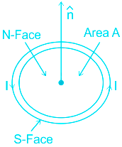
The direction of current in the circular current loop is in anticlockwise direction. Then the top face of the coil will behave as
Solution
CONCEPT:
- Current Loop As a Magnetic Dipole: A current-carrying circular coil behaves like a bar magnet whose magnetic moment is
M = NIA
Where N = number of turns in the coil, I = Current through the coil and A = Area of the coil
- The right-hand thumb rule of circular currents: According to this rule if the direction of current in the circular conducting coil is in the direction of folding fingers of the right hand, then the direction of the magnetic field will be in the direction of the stretched thumb.
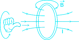
EXPLANATION:
- According to the question, the direction of current in the circular current loop is in an anticlockwise direction, therefore the top face of the coil will behave as North pole according to the Right-hand thumb rule of circular currents.
-
Question 38
5 / -1
If a diamagnetic substance is brought near the north or the south pole of a bar magnet, it is:
Solution
The correct answer is option 4) i.e. repelled by both the poles.
CONCEPT:
- Diamagnetic substance: Diamagnetic substances are those that are capable of freely getting magnetized when placed in an external magnetic field.
- The magnetization takes place in a direction that is opposite to the external magnetic field.
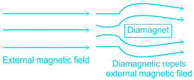
- When an external magnetic field is applied, the dipoles are induced in the diamagnetic materials arrange themselves in such a way that they start opposing the external magnetic field.
- The atoms of diamagnetic substances have paired electrons.
- A few examples of diamagnetic substances are Copper, Zinc, Bismuth, Silver, and Gold.
EXPLANATION:
- When a diamagnet is brought near a bar magnet it gets magnetized. The magnetization takes place in a direction that is opposite to the external magnetic field.
- When the diamagnet is at a distance from the bar magnet, the magnetic field deviates away from the diamagnet.
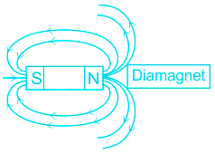
- When the diamagnet is brought more closer to the bar magnet, the magnetic field of the bar magnet has no space to deviate but acts as if the end of the diamagnet is a like pole and repels.
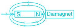
Hence, the diamagnet will get repelled by the poles of the bar magnet.
-
Question 39
5 / -1
The ratio of magnetic field due to a bar magnet on the axis and on the equator is-
Solution
CONCEPT:
- Bar Magnet: A bar magnet consists of two equal and opposite magnetic poles separated by a small distance. Poles are not exactly at the ends.
- The shortest distance between two poles is called effective length (Le) and is less than its geometric length (Lg) for bar magnets.
- Space around a magnetic pole or magnet or current-carrying wire within which its effect can be experienced is defined as a magnetic field.
- The magnetic field can be represented with the help of a set of lines or curves called magnetic lines of force.
The magnetic field on the axial line of a bar magnet is given by:
\({B_a} = \frac{{{\mu _0}}}{{4\;\pi }}\left( {\frac{{2M}}{{{d^3}}}} \right)\; \)
The magnetic field on the equatorial line of a bar magnet is given by:
\({B_e} = \frac{{{\mu _0}}}{{4\;\pi }}\left( {\frac{M}{{{d^3}}}} \right) \)
Where M is the magnetic moment of a bar magnet, μ0 is the permeability of free space and d is a distance of the point from the bar magnet
EXPLANATION:
The magnetic field on the axial line of a bar magnet is given by:
\({B_a} = \frac{{{\mu _0}}}{{4\;\pi }}\left( {\frac{{2M}}{{{d^3}}}} \right)\;\)
The magnetic field on the equatorial line of a bar magnet is given by:
\({B_e} = \frac{{{\mu _0}}}{{4\;\pi }}\left( {\frac{M}{{{d^3}}}} \right) \)
\(Ratio = \;\frac{{{B_a}}}{{{B_e}}} = \frac{{\frac{{{\mu _0}}}{{4\;\pi }}\left( {\frac{{2M}}{{{d^3}}}} \right)}}{{\frac{{{\mu _0}}}{{4\;\pi }}\left( {\frac{M}{{{d^3}}}} \right)}} = 2:1\)
-
Question 40
5 / -1
86Kr36 and 86Sr38 are examples of?
Solution
Concept:
- ATOMIC NUMBER: It is defined as the number of protons present in the nucleus. It is denoted by letter Z.
- MASS NUMBER: The total number of protons and neutrons present in a nucleus is called the mass number of the element. It is denoted by letter A.
Isobar
- Isobars are those elements which have a different atomic number but the same atomic mass.
- Their chemical property is different because there is a difference in the number of electrons.
- The example of two Isobars is Iron and Nickel.
- Both have the same mass number which is 58 whereas the atomic number of Iron is 26, and the atomic number of Nickel is 28.
Isotopes
- They are variants of a particular chemical element.
- While all isotopes of a given element share the same number of protons and electrons, each isotope differs from the others in its number of neutrons.
- For example, Carbon-12, Carbon-13 and Carbon-14 are three isotopes of the element carbon with mass numbers 12, 13 and 14 respectively.
Isotone
- Two nuclides are isotones if they have the same neutron number N, but different proton number Z.
- For example, Boron-12 and Carbon-13 nuclei both contain 7 neutrons, and so are isotones.
Isomer
- Isomers are ions or molecules with identical formulas but distinct structures.
- Isomers do not necessarily share similar properties.
Explanation:
From the above explanation, we can see that if the mass number is different but the atomic number is the same it is classified as isobars
In our case, Kr- 36 and Sr-38 are considered as isobars
-
Question 41
5 / -1
Meter bridge can be used to find resistance of
Solution
CONCEPT:
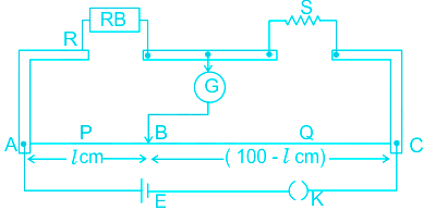
Meter Bridge:
- A meter bridge also called a slide wire bridge is an instrument that works on the principle of a Wheatstone bridge.
- A meter bridge is used in finding the unknown resistance of a conductor as that of in a Wheatstone bridge.
- In a meter bridge, a wire having a length of a uniform cross-section of about 1m is used.
- One known resistance and an unknown resistance are connected as shown in the figure.
- The one part of the galvanometer is connected in between the known and unknown resistances, whereas the other part of the wire is used to find the null point where the galvanometer is not showing any deflection.
- At this point, the bridge is said to be balanced.
EXPLANATION:
- The Meter bridge is most sensitive when all four arms have resistances of the same order. It is so only for moderate resistances.
- Meter bridges become insensitive if the resistances are either too low or too high.
- While we are measuring low resistances, the resistance of copper strips and connecting wire becomes comparable to that of unknown low resistance and there cannot be ignored. Hence option 2) is correct.
-
Question 42
5 / -1
Which of the following electromagnetic waves has the highest wavelength?
Solution
CONCEPT:
- Electromagnetic spectrum: It is a collection of a range of different waves in sequential order from radio to gamma electromagnetic waves.
Frequency (ν) = speed of light (c)/wavelength (λ)
- Radio waves: The lowest frequency portion comes in radio waves generally, has wavelengths range between 1 mm to 100 km or frequencies between 300 GHz to 3 kHz.
- There are several subcategories in between these waves like AM and FM radio.
- Microwaves: The part of the electromagnetic spectrum having the frequency more than that of radio waves and less than that of infrared waves are called microwaves.
- Infra-red light: It has the wavelength less than microwaves and greater than ultra-violet wave.
- Gamma rays: It has wavelength less than X-rays.
EXPLANATION:
- The radio waves has the longest wavelength among all given options. So option 2 is correct.
-
Question 43
5 / -1
Two ideal diodes are connected to a battery as shown in the circuit. The current supplied by the battery is
Solution
CONCEPT:
- Diode: A diode is a two-terminal electronic component that conducts current primarily in one direction; it has low resistance in one direction, and high resistance in the other.
There are two
- Forward Biasing:
- The forward bias means the positive region is connected to the p-terminal of the supply and the negative region is connected to the n-terminal of the supply.
- In forward biasing the external voltage is applied across the PN-junction diode.
- Reverse Biasing:
- In reversed bias, the negative region is connected to the positive terminal of the battery and the positive region is connected to the negative terminal.
- It creates a high resistive path in which no current flows through the circuit.
CALCULATION:
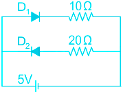
Given R1 = 10Ω, R2 = 20Ω
- The diode D1 is forward biased and D2 is reverse biased, so Diode D1 will allow the current, and D2 doesn't.
- Current can be calculated as
\(\Rightarrow I =\frac{V}{R}=\frac{5}{10}= 0.5 A\)
- The current supplied by the battery is 0.5 A.
-
Question 44
5 / -1
A magnetic dipole is freely suspended in a constant magnetic field of strength B. How much torque will be acted on the dipole if it is placed in such a way that the angle between plane of dipole and magnetic field is 0°?
Solution
CONCEPT:
- When a magnetic dipole of moment \(\vec M\) is held at an angle θ with the direction of a uniform magnetic field \(\vec B\), then it experiences a torque.
- The magnitude of the torque acting on the dipole is
⇒ τ = M B sin θ
CALCULATION:
Given - θ = 0°
- The magnitude of the torque acting on the dipole is
⇒ τ = M B sin θ
⇒ τ = M B sin 0° [∴ sin 0° = 0]
⇒ τ = 0
-
Question 45
5 / -1
The coil of the inductor element of 0.5 H is connected to an alternating source of frequency 50 Hz and its impedance will be -
Solution
Concept:
- Reactance: It is basically the inertia against the motion of the electrons in an electrical circuit.
- The unit of reactance is the ohm. In an electrical circuit.
\(⇒ Reactance= \frac{V}{I}\)
Where V = potential difference and I = current
- Impedance is a combination of resistance and reactance. It is essentially everything that resists the flow of electrons within an electrical circuit.
- Impedance of inductive circuit is given as
Znet = jωL
or
'Z = 2 π f L
Where f is frequency of AC Circuit, L is inductance
Calculation:
Given
frequency f = 50 Hz
Inductance :L = 0.5 H
'Z = 2 π f L = 2 × π × 0.5 × 50 = 157. 07
So, Z ≈ 157 Ω
So, the correct option is 157 Ω.
-
Question 46
5 / -1
The quality factor 'Q' equal to _________ and it is an indicator of the sharpness of the resonance in a RLC circuit.
Solution
CONCEPT:
RLC CIRCUIT:
- An RLC circuit is an electrical circuit consisting of an inductor (L), Capacitor (C), Resistor (R) it can be connected either parallel or series.
- When the LCR circuit is set to resonate (XL = XC), the resonant frequency is expressed as
\(f = \frac{1}{{2\pi }}\sqrt {\frac{1}{{LC}}}\)
\(Q=\frac{{{\omega }_{0}}L}{R}=\frac{1}{R}\sqrt{\frac{L}{C}}\)
Where,
XL & XC = Impedance of inductor and capacitor
L, R & C = Inductance, resistance, and capacitance
f = frequency
ω0 = angular resonance frequency
EXPLANATION:
From the above explanation, we can see that,
The quality factor of the RLC combination can be expressed as:
\(Q=\frac{{{\omega }_{0}}L}{R}\)
Hence option 2 is correct among all
-
Question 47
5 / -1
Two lights waves having intensities in the ratio of 9 : 4, produce interference. Then the ratio of maximum to minimum intensities in the resulting interference pattern will be
Solution
CONCEPT:
- Interference: The combination of two or more electromagnetic waveforms to form a resultant wave that may have greater, lower, or the same amplitude is called interference.
For two light sources s1 and s2, the resultant intensity (I) at some point p is given by:
\(I = {I_1} + {I_2} + 2√{{I_1} I_2}{cosϕ}\)
Where I1 and I2 are intensities of two light sources and ϕ is the phase difference between two sources.
CALCULATION:
Given that: I1/I2 = 9/4
Let I1 = 9k and I2 = 4k
Where k is a constant
\(I = {I_1} + {I_2} + 2√{{I_1} I_2}{cosϕ}\)
At maximum intensity:
Cosϕ = 1
So Imax = 9k + 4k + 2√(9k × 4k) = 25k
At minimum intensity:
Cosϕ = -1
So Imin = 9k + 4k - 2√(9k × 4k) = k
Ratio = Imax/Imin = 25k/k = 25: 1
So option 2 is correct.
-
Question 48
5 / -1
The focal length of a concave mirror is f in air. Its focal length in water (retractive index 4/3) will be
Solution
Concept:
Spherical Mirror:
- The mirror having spherical reflecting surfaces is called a spherical mirror.
- Concave mirrors have reflecting surfaces curved inward and convex mirrors have reflecting surfaces curved outward.
- The concave mirror converges the parallel rays of light to a point known as focus.
- The distance between the focus and center of the mirror is called the focal length.
- The focal length of a mirror depends upon the radius of the curvature of the mirror.
Refraction and Refractive Index
- The phenomenon of bending of light, when it travels from one transparent medium to another is called refraction.
- The amount of bending depends upon the refractive index of both mediums.
- The Refractive index of the medium is the ratio of the speed of the light in one medium to another medium.
Explanation:
- When a mirror is placed in water nothing will happen to its focal length.
- The focal length of the mirror depends upon the curvature of the mirror only.
- Focal length = (Radius of curvature) / 2
- The light will reflect in the same medium after reflecting by the mirror.
- There is no change in medium hence the refractive index of the medium of light while reflection.
- The focal length will remain f in water. f is the correct option.
Additional Information
- The lens is a transparent medium with a spherical outer surface.
- The focal length of the lens depends upon the medium in which it is placed.
- It is given by the lens maker formula.
\(\frac{1}{f} = \left ( \frac{μ_2}{μ_1} -1\right )\left ( \frac{1}{R_1} - \frac{1}{R_2} \right )\)
f is the focal length, μ2 is the refractive index of lens, μ1 is the refractive index of the medium., R1 and R2 are radii of both curvatures of the lens.
-
Question 49
5 / -1
In a A.C. circuit V = 100 sin ωt V and \(I=100 \sin \left(100t + \dfrac{\pi}{3}\right) A\), then average power loss will be:
Solution
CONCEPT:
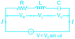
- The ac circuit containing the capacitor, resistor, and the inductor is called an LCR circuit.
- For a series LCR circuit, Impedance (Z) of the circuit is given by:
\(Z = \sqrt {{R^2} + {{\left( {{X_L} - {X_C}} \right)}^2}} \)
Where R = resistance, XL =induvtive reactance and XC = capacitive reactive
- The average power loss (P) in an A.C circuit is given by:
\(P=~{{V}_{rms}}{{I}_{rms}}Cosθ \)
Where Vrms = RMS voltage in the circuit, Irms = RMS current in the circuit, Φ = phase angle between the voltage and the current.
EXPLANATION:
Given - Potential difference (V) = 100 sin ωt V and \(I=100 \sin \left(100t + \dfrac{π}{3}\right) A\)
Therefore, the peak voltage (Eo) = 100, peal current (Io) = 100 and phase difference (θ) = π/3
- The average power loss (P) in an A.C circuit is given by:
\(\Rightarrow P=~{{V}_{rms}}{{I}_{rms}}Cosθ \)
\(\Rightarrow P =\frac{V_o}{\sqrt2}\frac{I_o}{\sqrt2} cos\,\theta \)
\(\Rightarrow P =\frac{100}{\sqrt2}\frac{100}{\sqrt2} cos\,\frac{\pi}{3} =2.5\times 10^3 \, W=2.5 \, kW\)
NOTE:
- There is no loss of energy in the capacitor and inductor in any circuit. They only store energy.
- The loss of energy is only due to a resistor.
-
Question 50
5 / -1
Which of the following is the correct sequence of electromagnetic waves arranged in their increasing order of wavelengths?
Solution
The correct answer is option 1) i.e. Infrared, Microwaves, Radio waves
CONCEPT:
- Electromagnetic spectrum: It is the arrangement of electromagnetic radiations according to their frequency or wavelength.
- The electromagnetic spectrum has a range of frequencies, wavelengths, and photon energies.
- Typically, electromagnetic waves travel at the speed of light in a vacuum.
- The electromagnetic spectrum is as follows:
EXPLANATION:
- From the electromagnetic spectrum, it is inferred that the wavelength increases in the order as Infrared < Microwaves < Radio waves. Therefore option 1 is correct.


 ×
×

 Sign in
 Profile
 Signout


