-
Question 1
5 / -1
Which one of the following law is based on the principle of conservation of electric charge?
Solution
CONCEPT:
There are two types of Kirchoff’s Laws:
- Kirchoff’s first law: This law is also known as junction rule or current law (KCL). According to it the algebraic sum of currents meeting at a junction is zero i.e. Σ i = 0.
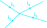
- In a circuit, at any junction, the sum of the currents entering the junction must be equal the sum of the currents leaving the junction i.e., i1 + i3 = i2 + i4
- This law is simply a statement of “conservation of charge” as if current reaching a junction is not equal to the current leaving the junction, the charge will not be conserved.
- Kirchoff’s second law: This law is also known as loop rule or voltage law (KVL) and according to it “the algebraic sum of the changes in potential in a complete traversal of a mesh (closed-loop) is zero”, i.e. Σ V = 0.
- This law represents “conservation of energy” as if the sum of potential changes around a closed loop is not zero, unlimited energy could be gained by repeatedly carrying a charge around a loop.
EXPLANATION:
- Kirchhoff’s Current Law (KCL) is based on the conservation of charge. So option 1 is correct.
- Kirchhoff’s Voltage Law (KVL) is based on the conservation of energy.
- Ohm's law gives the relation between electric current and potential difference.
- Coulomb's law gives the force between two charges separated by some distance.
-
Question 2
5 / -1
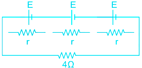
Find the equivalent internal resistance and potential of the given circuit.
Solution
CONCEPT:
- Grouping of Cells: In a series grouping of cell’s their emf’s are additive or subtractive while their internal resistances are always additive.
- Series grouping: In series grouping anode of one cell is connected to the cathode of other cells and so on.
- If n identical cells are connected in series
- Equivalent emf of the combination Eeq = nE
- Equivalent internal resistance req = nr
CALCULATION:
Given- emf of three cells = E1 = E2 = E3 = E and internal resistance = r1 = r2 = r3 = r
Equivalent emf of the combination is
⇒ Eeq = E1 + E2 + E3 = E + E + E = 3E
Similarly,
Equivalent internal resistance is
⇒ req = r1 + r2 + r3 = r + r + r = 3r
So option 3 is correct.
-
Question 3
5 / -1
In an observation with a telescope, having aperture of lens D, if the wavelength of the light is tripled then the resolving power of telescope will-
Solution
CONCEPT:
- Resolving power: When two point images are close to each other their images and diffraction patterns are also closed and overlap each other.
- The minimum distance between two objects which can been seen properly is called resolving power. Resolving power = 1/(Limit of observation).
- Resolving power for Microscope = (2μ sin θ)/λ
- Resolving power of Telescope = 1/dθ = D/(1.22 λ)
EXPLANATION:
- Resolving power of telescope ∝ 1/λ
- If λ is increased by 3 times, resolving power decreased by 3 times. So, Option 2 is correct.
-
Question 4
5 / -1
The power loss in a conductor of resistance 'R' across which a potential difference of 'V' is equal to which of the following?
Solution
CONCEPT:
- Electric Power: The rate at which electrical energy is dissipated into other forms of energy is called electrical power i.e.,
\(P = \frac{W}{t} = VI = {I^2}R = \frac{{{V^2}}}{R} \)
Where
V = Potential difference,
R = Resistance
I = current.
EXPLANATION:
From the above explanation, we can see that the relation between electric power/power loss in conduction, the voltage drop across conductor and resistance can be expressed as
\(P=\frac{{{V}^{2}}}{R}\)
Hence option 4 is correct among all
-
Question 5
5 / -1
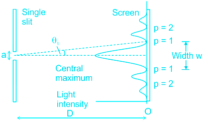
In an experiment of a single slit diffraction, the distance between the screen and the slit is increased by 5 cm. Then the angular width will -
Solution
CONCEPT:
- Diffraction of light at single slit: In the case of diffraction at single slit, we get central bright band with alternate bright and dark bands.
- Width of the central maxima β0 = 2λ D/d
- Angular width of central maxima (θ) = 2λ /d
- All the secondary fringes are of same width but the central fringe having width double.
- Width of secondary fringes = λ D/d
EXPLANATION:
- Angular width in single slit diffraction is
- θ = 2λ /d
- So, while increasing D (distance between slit and screen) there is no effect on it.
- Therefore it remains constant. So, option 3 is correct.
-
Question 6
5 / -1
The phenomenon which produces colours in a soap bubble is due to:
Solution
CONCEPT:
- Interference is the phenomena in which two waves superimpose to form a resultant wave the intensity which is greater or smaller than superimposed waves.
- Interference is of two types
- Constructive interference: The process in which the intensity and amplitude of the resultant wave are greater than two superimposed waves.
- Destructive interference: The process in which the intensity and amplitude of the resultant wave are lesser than two superimposed waves.
EXPLANATION:
- The colours in a soap bubble are produced due to interference
- The colours are seen in a soap bubble due to the interference of light reflecting off from the front and back surfaces of the soap film. Hence, option 3 is the answer.
-
Question 7
5 / -1
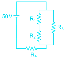
Find the potential difference across the resistance R2 in the given circuit (Given R1 = 15 ohm, R2 = 15 ohm, R3 = 30 ohm and R4 = 35 ohm)
Solution
CONCEPT:
Ohm’s law:
- Ohm’s law states that electric current is proportional to voltage and inversely proportional to resistance.
I.e. I=V/R
⇒ V=IR.
Where, V = Voltage, I = current, and R = Resistance
Resistance:
- The measurement of the opposition of the flow of electric current through a conductor is called the resistance of that conductor. It is denoted by R.
Resistances in parallel:
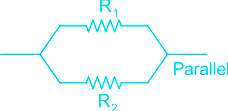
- When the terminals of two or more resistances are connected at the same two points and the potential difference across them is equal is called resistances in parallel.
- The net resistance/equivalent resistance(R) of resistances in parallel is given by:
\(\frac{1}{R} = \frac{1}{{{R_1}}} + \frac{1}{{{R_2}}}\)
CALCULATION:
Given: R1 = 15Ω, R2 = 15 Ω, R3 = 30 Ω, R4 = 35 Ω
- Since resistors R1 and R2 are connected in series,
R12 = R1 + R2 = 15 + 15 = 30Ω
- Now, resistors R12 and R3 are connected parallel,
\(\frac{1}{{{R_{123}}}} = \frac{1}{{{R_{12}}}} + \frac{1}{{{R_3}}} = \frac{1}{{30}} + \frac{1}{{30}} = \frac{1}{{15}} \)
R123 = 15Ω
- Since, R123 and R4 are connected in series,
RT = R123 + R4 = 15 + 35 = 50Ω
RT = 50Ω
- Current flowing through the circuit,
\(I = \frac{V}{{{R_T}}} = \frac{{50}}{{50}} = 1\;Amp\)
I = 1 amp
As resistance R12 = R3
- So, current will flow through each branch is same i.e. = 0.5 Amp
Voltage across R12 is
V12 = I12 × R12
V12 = 0.5 × 30
V12 = 15 v
- Since R1 and R2 are equal so voltage drop will be equal across both the resistors.
V1 = V2 = 0.5 × 15
V1 = v2 = 7.5 V
V2 = 7.5 V
 Additional Information
| Series Combination | Parallel Combination |
| Two resistors are said to be in series if only one of their endpoints is joined, if the third resistor is joined at end of one point only, then all three resistors are in series (fig.a). | Two or more resistors are said to be in parallel if one end of all the resistors is joined together and similarly the other ends joined together (fig. b). |
| In series, voltage is divided through each of the connected resistors. | In parallel, the current is divided through each connected resistor. |
| In series, the Current will be the same throughout the circuit. | In parallel, Voltage will be the same throughout the circuit. |
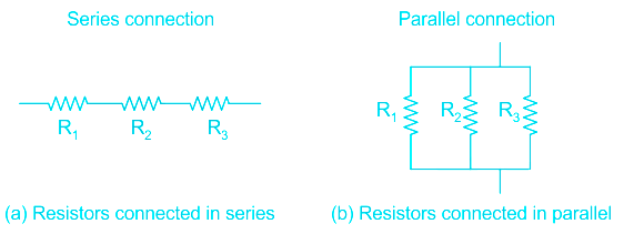
Addition in Series Addition in Parallel
Req = R1 + R2 + R3 \(\frac{1}{{{R_{eq}}}} = \frac{1}{{{R_1}}} + \frac{1}{{{R_2}}} + \frac{1}{{{R_3}}}\)
-
Question 8
5 / -1
The refractive index of a thin prism of prism angle 5° is 1.4. Find the angle of deviation of light ray falling on this prism.
Solution
Concept:
Dispersion of light:
- The phenomenon in which a white light ray when falls on a prism gets separated into its component colors is called as dispersion of light.
- Different colors of different wavelength experience different degree of deviation and hence when put through refraction, white light splits into its constituent colors.
- When light rays fall on the prism then there is deviation in the path of the ray after refraction through prism.
- For a thin prism deviation angle is very small.
The deviation angle for a thin prism of prism angle A is given by:
δ = (μ - 1) A
Where μ is the refractive index of the Prism
Explanation:
Given that;
Refractive index = μ = 1.4
Angle of prism = A = 5°
Angle of deviation = δ = (μ - 1) A = (1.4-1) × 5 = 2°
-
Question 9
5 / -1
Calculate the half life of a substance X, having decay rate constant of 2.31 × 10⁻²
Solution
CONCEPT:
- The half-life of a radioactive element (T1/2): The time interval in which the mass of a radioactive substance or the number of atoms reduced to half of its initial value.
- The expression for the half-life is
\(\Rightarrow T_{\frac{1}{2}} = \frac{0.693}{λ }\)
Where λ = is the decay rate constant
CALCULATION:
Given:
\(\lambda = 2.31\times 10^{-2}\)\(\Rightarrow T_{\frac{1}{2}} = \frac{0.693}{λ }\)
\(\Rightarrow T_{\frac{1}{2}} = \frac{0.693}{2.31\times 10^{-2} }= 30\ year\)
- Hence, option (2) is correct.
-
Question 10
5 / -1
The frequency employed for TV broadcasting is normally of the order of -
Solution
The correct answer is 30 - 300 MHz.
 Key Points
- Generally, 30 MHz to 300 MHz frequency is used for the television broadcasting signals.
- TV transmission is a broadcast communication system.
- The broadcast system for tv transmission uses skywave propagation which is a long-distance communication.
- Skywave propagation is used by short wave broadcast services in the frequency range of a few MHz to 40 MHz, long-distance communication can be achieved by the ionospheric reflection of radio waves. This is called skywave propagation.
- Television and satellite systems use space wave mode of propagation.
- In India, the Pal B and Pal G systems have been adopted for the VHF and UHF bands respectively.
- A TV Channel in the VHF band ( 30-300 MHZ) requires a bandwidth of 7 MHz whereas, in the UHF band( 300-3000 MHz), it requires a bandwidth of 8 MHz.
-
Question 11
5 / -1
An atom has a mass number of 23 and atomic number 11. The number of protons is ________.
Solution
CONCEPT:
- The Atomic mass is the sum of protons and neutrons.
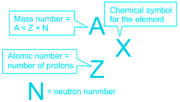
- In the nucleus of an atom, there are protons and neutrons.
Number of protons = Atomic number of an element.
Nuclei = neutron + proton
EXPLANATION:
Given that: mass number = 23 and atomic number = 11.
Number of protons = Atomic number = 11
IMPORTANT POINTS:
-
Question 12
5 / -1
Which one of the following statements is NOT true about the sound waves?
Solution
CONCEPT:
Mechanical waves:
- The oscillation of matter which is responsible for the transfer of energy through a medium is called a mechanical wave.
- The mechanical wave always needs a medium to travel.
- It can’t travel through a vacuum.
- The wave which propagates in a solid, liquid, or gaseous medium is called an elastic wave.
There are two types of mechanical waves:
Transverse waves:
- The wave in which the movement of the particles is at right angles to the motion of the energy is called a transverse wave.
- Light is an example of a transverse wave.
Longitudinal wave:
- The wave in which the movement of the particles is parallel to the motion of the energy is called a longitudinal wave.
- A sound wave is an example of a longitudinal wave.
EXPLANATION:
- Sound waves need a medium to travel. Hence, it can propagate through the water.
- The speed of sound waves in steel is more than its speed in the air since the molecules in solid material are closely packed together and can transfer the energy faster than molecules in liquid which are loosely packed.
- A sound wave is an example of an elastic wave and longitudinal wave and due to the elastic wave nature of the sound wave, it can’t travel in a vacuum.
-
Question 13
5 / -1
The focal length of a mirror is f. If it is placed in water (n = 4/3), its focal length will be:
Solution
Concept:
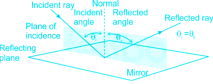
- Reflection: The phenomena in which light ray is sent back into the same medium from which it is coming, on interaction with boundary, is called reflection.
- Laws of reflection:
- Angle of incidence (θ i ) = Angle of reflection (θ r )
- The incident ray, the reflected ray, and normal to the surface of incidence always lies in the same plane.
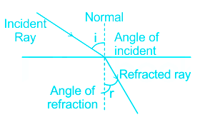
- Refraction: When a ray of light passes from one medium to another it suffers a change in direction at the boundary of two media is called refraction.
- The change in direction because the speed of light travels at different speeds in different mediums.
- Refractive Index of a medium defines that it is denser or rarer
- Refractive Index = Speed of light in Vacuum /speed of light in that medium.
- Refractive Index = η =c/v where, c = Speed of light in Vacuum, v= speed of light in that medium.
Explanation:
Mirror works on the principle of reflection,
Where, law of reflection doesn't depend on the refractive index of medium.
So, when a mirror of focal length f (in air ) is immersed in water then, the focal length of the mirror in water remains constant e.g., f.
Hence the correct answer is f.
Additional Information
In the case of spherical lens, its focal length changes with the lens maker formula.
The lens maker’s formula is given by:
\(\frac{1}{f} = \left( {n - 1} \right)\left( {\frac{1}{{{R_1}}} - \frac{1}{{{R_2}}}} \right)\)
Where, f is the focal length (half the radius of curvature), n is the refractive index of the material used, R1 is the radius of curvature of sphere 1 and R2 is the radius of curvature of sphere 2
-
Question 14
5 / -1
When a dielectric material of K dielectric constant is inserted between two parallel plate capacitor the electric field in between region of the plates
Solution
Correct option-2
Concept:
- The capacitor is an arrangement of two-conductor generally carrying charges of equal magnitudes and opposite signs and separated by an insulating medium. The non-conductive or insulating region can either be an electric insulator or vacuum such as glass, paper, air, or semi-conductor called a dielectric.
- It is a device that is used to store electrical energy.
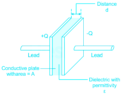
Parallel plate capacitors-
- It is an arrangement of electrodes and insulating material or dielectric.
- Parallel plate capacitors can be defined as: when two parallel plates separated by a very small distance as compared with the dimension are connected across a battery, the plates are charged and an electric field is established between them, and this setup is known as the parallel plate capacitor.
Explanation:
The expression of the electric field in-between region of parallel plate capacitors without inserting the dielectric is given as-
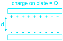
\(E=\frac{Q}{A{{\varepsilon }_{0}}d}\)
where,
- Q is the charge on each plate.
- A is the area of each plate.
- \({{\varepsilon }_{0}}\) is the permittivity of free space and
- d is the separation between the plates
When a dielectric medium of dielectric constant K is placed in between the plates Then
The electric field in between region is given as-
\(E'=\frac{Q}{AK{{\varepsilon }_{0}}d}=\frac{E}{K}\)
\(\therefore E'=\frac{E}{K}\)
Thus, On inserting the dielectric in between parallel plate capacitors electric field decreases by a factor of K.
Hence, Option-2 is the correct answer.

- Dielectric is a material that does not have a free charge carrier for conduction. They however contain positive and negative charges which are bound together.
- They can be easily polarized which means charges inside the material will show response to an electric field applied externally.
- In Dielectric material, the external field will compel the molecules to align the individual dipole moment along the direction of the applied field.
- They are used to store energy. These materials exist in solid, liquid, and gaseous forms. Some examples of dielectric materials are:
- Solid Dielectrics – Plastic, Ceramic, Glass, and Mica
- Dielectric Liquid – Distilled Water.
- Dielectric Gas – vacuum, nitrogen, Dry Air, and helium.
-
Question 15
5 / -1
Two current-carrying long wires of equal length are placed parallel to each other and separated by a small distance, if the current in both the wires is halved then the force per unit length on the wires will:
Solution
CONCEPT:
The force between two parallel currents:
- We know that there exists a magnetic field due to a conductor carrying a current.
- And an external magnetic field exerts a force on a current-carrying conductor.
- Therefore we can say that when two current-carrying conductors placed nearby each other will exert (magnetic) forces on each other.
- In the period 1820-25, Ampere studied the nature of this magnetic force and its dependence on the magnitude of the current, on the shape and size of the conductors, as well as, the distances between the conductors.
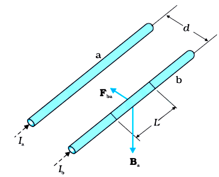
- Let two long parallel conductors a and b separated by a distance d and carrying (parallel) currents Ia and Ib respectively.
- The magnitude of the magnetic field intensity due to wire a, on the wire b is,
\(\Rightarrow B_a=\frac{\mu_oI_a}{2\pi d}\)
- The magnitude of the magnetic field intensity due to wire b, on the wire a is,
\(\Rightarrow B_b=\frac{\mu_oI_b}{2\pi d}\)
- The conductors 'a' and ‘b’ carrying a current Ia and Ib respectively will experience sideway forces due to magnetic field Bb and Ba respectively.
EXPLANATION:
- If two current-carrying long wires A and B are separated by a very small distance and placed parallel to each other. Then the force per unit length on wire A and wire b is given as,
\(\Rightarrow f_{ab}=f_{ba}=f=\frac{\mu_o I_aI_b}{2\pi d}\) -----(1)
Where Ia = current in the wire A, Ib = current in the wire B, and d = distance between the wires
- If the current in both the wires is halved, then,
\(\Rightarrow I_{a}^{'}=\frac{I_a}{2}\)
\(\Rightarrow I_{b}^{'}=\frac{I_b}{2}\)
So the new force per unit length on wire A and wire B is given as,
\(\Rightarrow f_{ab}^{'}=f_{ba}^{'}=\frac{\mu_o I_{a}^{'}I_{b}^{'}}{2\pi d}\)
\(\Rightarrow f_{ab}^{'}=f_{ba}^{'}=\frac{\mu_o I_{a}I_{b}}{2\times2\times2\pi d}\)
\(\Rightarrow f_{ab}^{'}=f_{ba}^{'}=\frac{\mu_o I_{a}I_{b}}{4\times2\pi d}\) -----(2)
By equation 1 and equation 2,
\(\Rightarrow f_{ab}^{'}=f_{ba}^{'}=\frac{f}{4}\)
- Hence, option 2 is correct.
Additional Information
The magnitude of the force on the segment L of the wire 'a' due to magnetic field Bb is given as,
\(\Rightarrow F_{ab}=\frac{\mu_o I_aI_b}{2\pi d}L\)
The magnitude of the force on the segment L of the wire 'b' due to magnetic field Ba is given as,
\(\Rightarrow F_{ba}=\frac{\mu_o I_aI_b}{2\pi d}L\)
The magnitude of the force per unit length on wire a and wire b is given as,
\(\Rightarrow f_{ab}=f_{ba}=\frac{\mu_o I_aI_b}{2\pi d}\)
 Important Points
- When the current flows in the same direction in the two parallel wires then both wires attract each other and if the current flows in the opposite direction in the two parallel wires then both wires repel each other.
-
Question 16
5 / -1
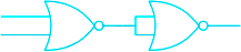
Identify the logic operation performed by the circuit given here.
Solution
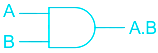
AND Gate: The Logic AND Gate is a digital logic circuit whose output HIGH only when all the inputs are 1 (HIGH) otherwise output will be LOW.
OR Gate: The Logic OR Gate is a digital logic circuit whose output goes HIGH only when any one or more than one of its inputs is HIGH.
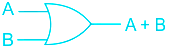
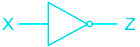
NOT Gate: The Logic NOT Gate is the most basic of all the logic gates and is often referred to as an Inverting Buffer or simply an Inverter
NAND Gate: The logic Gate is obtained after adding NOT Gate after AND Gate.
\(Y=\overline{A.B}\)
NOR Gate: The logic Gate is obtained after adding NOT Gate after OR Gate.
\(Y=\overline{A+B}\)


EXPLANATION:
A and B is the inputs, the result from first NOR gate is C. This again becomes two inputs which gives result Y from the second NOR Gate.
So the table will be as given
| A | B | C | C | Y |
| 0 | 0 | 1 | 1 | 0 |
| 0 | 1 | 0 | 0 | 1 |
| 1 | 0 | 0 | 0 | 1 |
| 1 | 1 | 0 | 0 | 1 |
So in the given table resultant Y shows results as OR Gate.
So the correct answer is option 3.
-
Question 17
5 / -1
Light with longest wave length in visible spectrum is _____?
Solution
CONCEPT:
- Light or visible light commonly refers to electromagnetic radiation that can be detected by the human eye.
- The entire electromagnetic spectrum is extremely broad, ranging from low energy radio waves with wavelengths that are measured in meters to high energy gamma rays with wavelengths that are less than 1 × 10-11 meters.
- Visible light is usually defined as having wavelengths in the range of 400-700 nanometers (nm), or 4 × 10⁻⁷ to 7 × 10⁻⁷m between the infrared (with longer wavelengths) and the ultraviolet (with shorter wavelengths).
- This wavelength means a frequency range of roughly 430-750 terahertz(THz).
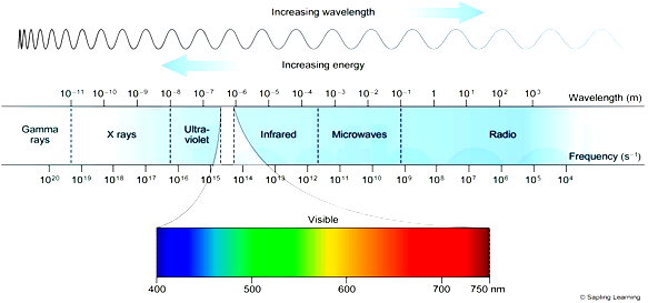
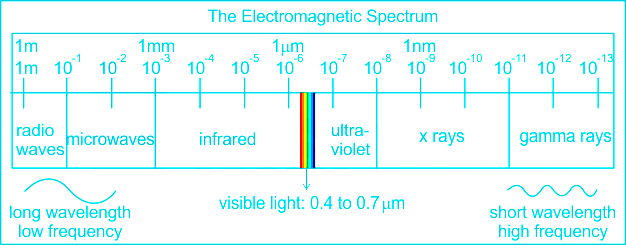
EXPLANATION:
- As we can see in the diagram that Red light has the longest wavelength.
- Hence option 2 is the answer.
-
Question 18
5 / -1
The forbidden energy band gap in conductors, semiconductors and insulators are Eg1, Eg2 and Eg3 respectively. The relation among them is
Solution
CONCEPT:
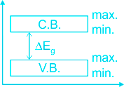
- Forbidden energy gap (ΔEg): The energy gap between the conduction band and valence band is known as the forbidden energy gap i.e.,
ΔEg = (C.B)min - (V.B)max
- No free electron is present in the forbidden energy gap.
- The width of the forbidden energy gap depends upon the nature of the substance.
- As the temperature increases, the forbidden energy gap decreases very slightly.
EXPLANATION:
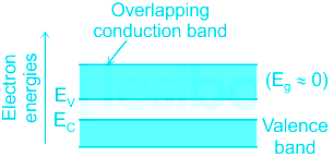
- In a conductor, the conduction band is partially filled and the valanced band is partially empty or when the conduction and valance bands overlap. When there is overlap electrons from the valence band can easily move into the conduction band.
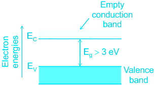
- In an insulator, there exists a large bandgap between the conduction band and valence band Eg (Eg > 3 eV). There are no electrons in the conduction band, and therefore no electrical conduction is possible.
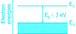
- In semiconductors, there exists a finite but small band gap between the conduction band and valence band (Eg < 3 eV). Because of the small bandgap, at room temperature, some electrons from the valence band can acquire enough energy to cross the energy gap and enter the conduction band.
- Therefore, the forbidden energy bandgap in conductors, semiconductors, and insulators are in the relation Eg1 < Eg2 < Eg3. Therefore, option 2 is correct.
-
Question 19
5 / -1
Input characteristics of transistor in CE mode represents resistance that is of value:
Solution
Explanation:
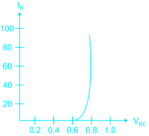
The Input resistance of the transistor is equal to the reciprocal of the slope of the output characteristic which is shown figure.
Input Characteristics:
The output voltage VCE is kept constant and P.D. between the base and emitter VBE is gradually increased. The base current IB is measured. The curves obtained by plotting base current on the y-axis and VBE on the x-axis at different values of VCE are called input characteristics of the transistor. The reciprocal of the slope of the curve in the linear region gives input resistance Ri. For CE mode is very small.
So input resistance is very small for BJT in CE mode of operation.
-
Question 20
5 / -1
Find the angle of dip at a certain place where the horizontal and vertical components of the earth’s magnetic fields are same.
Solution
CONCEPT:
- The magnetic Declination (θ): It is the angle between geographic and magnetic meridian planes.
- Declination at a place is expressed at θ° E or θ° W depending upon whether the north pole of the compass needle lies to the east or to the west of the geographical axis.
- The angle of inclination or Dip (Φ): It is the angle between the direction of the intensity of the total magnetic field of earth and a horizontal line in the magnetic meridian.
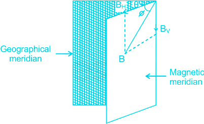
The angle of dip is given by:
ϕ = tan-1(BV / BH)
where BV = vertical component of earth's magnetic field and BH = horizontal components of earth's magnetic field.
EXPLANATION:
Given that, BV = BH
The angle of dip is given by
ϕ = tan-1(BV / BH)
From given ϕ = tan-1(1) = 45°
Important Points
- At the magnetic poles, a dip needle stands vertical (dip=90 degrees), the horizontal intensity is zero, and a compass does not show direction.
- At the north magnetic pole, the north end of the dip needle is down.
- At the south magnetic pole, the north end is up.
- At the magnetic equator, the dip or inclination is zero.
Key Points
- The axis of the dipole is offset from the axis of the Earth's rotation by approximately 11 degrees.
- The lines of forces due to the earth's horizontal component of the magnetic field are parallel straight lines.
-
Question 21
5 / -1
An ideal transformer has 500 and the 1000 turns in the primary and the secondary coil. If the DC voltage of 120 V is applied to the primary coil, then the emf produced at the secondary coil will be:
Solution
CONCEPT:
- A Transformer is used to convert low voltage (or high current) to high voltage (or low current) and high voltage to low voltage.
- The transformer works on the principle of Faraday's law of electromagnetic induction and mutual induction.
- The primary coil has Np turns and the other coil, called the secondary coil, has Ns turns.
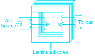
- In a transformer, the voltage in secondary is calculated by
\(\Rightarrow \frac{E_{S}}{S_{P}}=\frac{I_{P}}{I_{S}}=\frac{N_{S}}{N_{P}}\)
EXPLANATION:
Given DC voltage EP = 120 V (Primary coil)
- To induce emf in the secondary coil of the transformer, the magnetic flux associated with the secondary coil must change with respect to time.
- When the DC voltage is applied at the primary coil of the transformer, the magnetic flux associated with the coil will remain constant with respect to time. So the emf will not induce at the secondary coil.
- Therefore when the DC voltage is applied at the primary coil, the induced emf in the secondary coil will be zero.
- Hence, option 4 is correct.
Additional Information
Mutual-inductance
- When two coils are brought in proximity with each other the magnetic field in one of the coils tends to link with the other. If this magnetic field of the first coil is changed then the magnetic flux associated with the second coil changes and this leads to the generation of voltage in the second coil.
- This property of a coil that affects or changes the current and voltage in a secondary coil is called mutual inductance.
\(⇒ M_{12}=N_{1}\frac{ϕ_{1}}{I_{2}}\)
-
Question 22
5 / -1
De Broglie relation is represented by ______.
Solution
Explanation:
de Broglie wavelength of electrons:
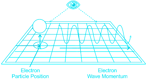
- Louis de Broglie theorized that not only light possesses both wave and particle properties, but rather particles with mass - such as electrons - do as well,i.e. matter has dual nature.
- The wavelength of material waves is also known as the de Broglie wavelength.
- de Broglie wavelength (λ) of electrons can be calculated from Plancks constant h divided by the momentum of the particle
- So, according to de Broglie, every object has a dual nature- a particle and a wave nature whose wavelength is given by
\(\lambda = \frac{h}{{mv}}\)
or \(\lambda = {h\over p};p=mv\)
where m is the mass of the particle,v is the velocity of the particles and h is the Planck's constant.
- The wave nature is predominant in particles of small mass like electrons and negligible in bodies of large masses.
- Waves are dispersed over a wide region and not confined.
Hence, De Broglie relation is represented by λ = h/p.
Important Points
- The wave associated with each moving particle is called matter waves.
- Characteristics of Matter waves:
- The lighter the particle, the greater is the de Broglie wavelength.
- The higher the velocity of the particle, the smaller is its de Broglie wavelength.
- The de Broglie wavelength of a particle is independent of the charge or nature of the particle.
- The matter waves are not electromagnetic in nature. Only charged particles produce electromagnetic waves.
-
Question 23
5 / -1
An electric dipole of dipole moment p is placed parallel to a uniform electric field E. The work done required to rotate the dipole by an angle 180° will be:
Solution
CONCEPT:
Electric dipole
- When two equal and opposite charges are placed at a very small distance to each other then this arrangement is called an electric dipole.
- The electric dipole moment is defined as the product of the magnitude of one charge and the distance between the charges in an electric dipole.
⇒ P = q × 2r
Where 2r = distance between the two charges
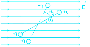
- Work done required to rotate an electric dipole in an external uniform electric field from the angle θ1 to θ2 is given as,
⇒ W = pE(cosθ1 - cosθ2)
Where θ1 and θ2 = initial and the final angle between the dipole and the electric field
CALCULATION:
Given p = dipole moment, E = electric field
- When the electric dipole is placed parallel to the electric field the angle between the dipole and the electric field is given as,
⇒ θ1 = 0°
When the dipole is rotated by an angle of 180°,
⇒ θ2 = 180°
So the work done is given as,
⇒ W = pE(cosθ1 - cosθ2)
⇒ W = pE(cos 0° - cos180°)
⇒ W = 2pE
- Hence, option 1 is correct.
-
Question 24
5 / -1
Which of the following statements is true with reference to Coulomb's law?
Solution
CONCEPT:
- Coulomb's law in Electrostatics: It state’s that force of interaction between two stationary point charges is directly proportional to the product of the charges, and inversely proportional to the square of the distance between them and acts along the straight line joining the two charges.
F ∝ q1 × q2
\(F \propto \;\frac{1}{{{r^2}}}\)
\(F = K\frac{{{q_1}\; \times \;{q_2}}}{{{r^2}}}\)
Where K = constant called electrostatic force constant.
- The value of K depends on the nature of the medium between the two charges and the system of units chosen
EXPLANATION:
- It accounts for the forces that bind atoms to form molecules. Therefore option 1 is incorrect.
- It correctly describes the force between the positive nucleus and negative electrons in an atom. Therefore option 2 is incorrect
- It accounts for the forces that bind atoms and molecules to form solids and liquids. Therefore option 3 is incorrect.
- The electrostatic forces between two charges that can result in the attraction of the two charges or can cause repulsion between the charges. Therefore option 4 is correct.
-
Question 25
5 / -1
The torque experienced by a magnetic dipole, having dipole moment M, when placed in a uniform magnetic field of intensity B is:
Solution
Concept:
A rectangular coil always acts as a magnetic dipole of dipole moment M.
The dipole moment of the coil (M) = N I A
N is the number of turns
I is current in the coil and
A is the area of the rectangular coil
The torque of the magnetic field on any magnetic dipole moment is given by;
T = M × B = MB Sinθ
M × B = cross product of Area vector A and magnetic field vector B
θ = the angle between area vector A and magnetic field B.
Since M = N I A, the torque on the rectangular coil (T) will be:
M × B = MB sinθ = N I A B Sinθ
Observations:
- According to the above formula of the torque on a rectangular coil in a magnetic field, torque will be large when the number of turns is large.
- If the magnetic field is perpendicular to the plane of the coil then it will be along the area vector. So the angle between the area vector and the magnetic field will be zero and finally, the torque will be zero.
- If the area will be small then torques will also be small.
-
Question 26
5 / -1
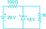
In the circuit shown below 18 V Zener diode has zero Zener resistance and a knee current of 2 mA. The minimum value of R so that voltage across it does not fall below 18 V is:
Solution
Concept:
Zener diode as voltage regulator:
- Zener diodes are used in circuits to maintain a fixed voltage across a load.
- It breaks down at a specific voltage when it is reverse biased. This means that a Zener diode will stop a reverse current from flowing through it until the reverse voltage applied across it reaches a fixed value known as the breakdown voltage (Vz).
- It maintains the voltage at its breakdown voltage as long as the supply voltage is above this value.
Zener Knee Current:
The reverse current flows through the Zener diode at the break-down voltage.
Calculations:
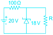
\(\rm \frac{{\left( {20 - 18} \right)}}{{100}} = {I_Z} + {I_R}\)
\(\rm \frac{2}{{100}} = {I_{zmin}} + {I_{R\left( {max} \right)}}\)
\(\rm 2 \times {10^{ - 2}} = 2 \times {10^{ - 3}} + \frac{18}{{{R_{min}}}}\)
\(\rm {R_{min}} = \frac{18}{{18 \times {{10}^{ - 3}}}} = 1000\ \Omega\)
-
Question 27
5 / -1
A charged conductor is placed in an external electric field. The potential inside the conductor is
Solution
CONCEPT:
Conductors:
- Conductors contain mobile charge carriers. In metallic conductors, these charge carriers are electrons.
- In an external electric field, they drift against the direction of the field.
- In electrolytic conductors, the charge carriers are both positive and negative ions.
Important results regarding electrostatics of conductors:
- Inside a conductor, the electrostatic field is zero.
- At the surface of a charged conductor, the electrostatic field must be normal to the surface at every point.
- The interior of a conductor can have no excess charge.
- The electrostatic potential is constant throughout the volume of the conductor and has the same value (as inside) on its surface.
- The electric field at the surface of a charged conductor is \( E=\frac{\sigma}{\varepsilon_{0}} ̂{n}\)
- Electrostatic shielding.
EXPLANATION:
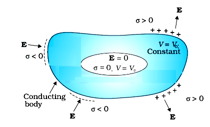
- The electric field inside a conductor is always zero, thus
- The potential inside a conductor is constant everywhere and the same as that at the surface.
- In this case of a charge-neutral conductor placed in an external electric field, charges will be induced on the surface.
- Due to these induced charges on the surface, the potential at the surface and inside will not be zero.
- But the potential will still have a constant value everywhere inside the conductor. Therefore option 3 is correct.
Additional Information
- Inside a conductor, the electrostatic field is zero.
- There may be an external electrostatic field. A conductor has free electrons. As long as the electric field is not zero, the free charge carriers would experience force and drift. In the static situation, the free charges have so distributed themselves that the electric field is zero everywhere inside.
- At the surface of a charged conductor, the electrostatic field must be normal to the surface at every point.
- If E were not normal to the surface, it would have some non-zero component along the surface. Free charges on the surface of the conductor would then experience force and move. Therefore, E should have no tangential component.
- The interior of a conductor can have no excess charge.
- A neutral conductor has equal amounts of positive and negative charges in every small volume or surface element. When the conductor is charged, the excess charge can reside only on the surface. This can be derived from Gauss' Law
- The electrostatic potential is constant throughout the volume of the conductor and has the same value (as inside) on its surface.
- This follows from results 1 and 2 above. Since E = 0 inside the conductor and has no tangential component on the surface, no work is done in moving a small test charge within the conductor and on its surface. That is, there is no potential difference between any two points inside or on the surface of the conductor.
- The electric field at the surface of a charged conductor is
- Where σ is the surface charge density and is a unit vector normal to the surface in the outward direction. For σ > 0, the electric field is normal to the surface outward; for σ < 0, the electric field is normal to the surface inward.
- Electrostatic shielding.
- Consider a conductor with a cavity, with no charges inside the cavity. A remarkable result is that the electric field inside the cavity is zero. Whatever be the size and shape of the cavity and whatever be the charge on the conductor and the external fields in which it might be placed. The electric field inside the cavity of any conductor is zero. All charges reside only on the outer surface of a conductor with a cavity.
-
Question 28
5 / -1
Write the frequency of EM waves spectrum in increasing order.
Solution
CONCEPT:
Electromagnetic spectrum: It is a collection of a range of different waves in sequential order from radio to gamma electromagnetic waves.
- Frequency (ν) = speed of light (c)/wavelength (λ)
EXPLANATION:
Thus the increasing order of frequency:
Radio < microwave < infrared wave < Visible light < ultraviolet < X-rays < Gamma rays
-
Question 29
5 / -1
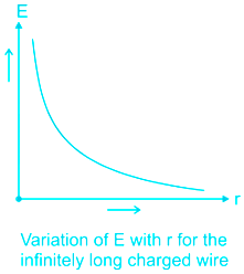
According to Gauss’s law, the electric field due to an infinitely long thin charged wire varies as:
Solution
CONCEPT:
Gauss’s Law: Total electric flux through a closed surface is 1/εo times the charge enclosed in the surface i.e. \({\rm{\Phi }} = \frac{q}{{{\epsilon_o}}}\)
But we know that Electrical flux through a closed surface is \(\oint \vec E \cdot \overrightarrow {ds} \)
\(\therefore\oint \vec E \cdot \overrightarrow {ds} = \frac{q}{{{\epsilon_o}}}\)
Where, E = electric field, q = charge enclosed in the surface and εo = permittivity of free space.
EXPLANATION:
Electric field due to line charge:
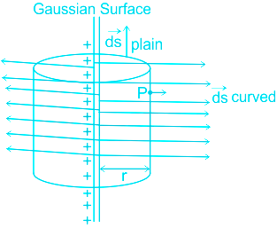
Electric field due to an infinitely long straight conductor is
\(E=\frac{\lambda }{2\pi {{\epsilon }_{o}}r}~\)
Where λ = linear charge density, r = radius of the cylinder, and εo = permittivity of free space.
From the above equation, it is clear that the electric field of an infinitely long straight wire is proportional to 1/r. Hence option 1 is correct.
-
Question 30
5 / -1
The semiconductor used for the fabrication of visible LEDs must at least have a band gap of:
Solution
CONCEPT:
Light Emitting Diode:
- It is a heavily doped p-n junction that under forward bias emits spontaneous radiation.
- The diode is encapsulated with a transparent cover so that emitted light can come out.
- When the diode is forward biased, electrons are sent from n to p (where they are minority carriers) and holes are sent from p to n (where they are minority carriers).
- At the junction boundary, the concentration of minority carriers increases compared to the equilibrium concentration (i.e., when there is no bias).
- Thus at the junction boundary on either side of the junction, excess minority carriers are there which recombine with majority carriers near the junction.
- On recombination, the energy is released in the form of photons. Photons with energy equal to or slightly less than the bandgap are emitted.
- When the forward current of the diode is small, the intensity of light emitted is small.
- As the forward current increases, the intensity of light increases and reaches a maximum. Further, an increase in the forward current results in a decrease in light intensity.
- LEDs are biased such that the light-emitting efficiency is maximum.
- The V-I characteristics of a LED are similar to that of a-Si junction diode.
- But the threshold voltages are much higher and slightly different for each color.
- The reverse breakdown voltages of LEDs are very low, typically around 5V.
- So care should be taken that high reverse voltages do not appear across them.
- LEDs can emit red, yellow, orange, green, and blue light that are commercially available.
- The semiconductor used for the fabrication of visible LEDs must at least have a bandgap of 1.8 eV (spectral range of visible light is from about 0.4 μm to 0.7 μm, i.e., from about 3 eV to 1.8 eV).
- The compound semiconductor Gallium Arsenide – Phosphide is used for making LEDs of different colors.
- Gallium Arsenide is used for making infrared LED.
EXPLANATION:
- We know that the semiconductor used for the fabrication of visible LEDs must at least have a bandgap of 1.8 eV (spectral range of visible light is from about 0.4 μm to 0.7 μm, i.e., from about 3 eV to 1.8 eV). Hence, option 3 is correct.
-
Question 31
5 / -1
If the last band on the carbon resistor is absent, then the tolerance is
Solution
CONCEPT:
- Resistances are available in small as well as in large values.
- The resistors are generally painted by a specific colour and a specific code is assigned to them. This is called colour coding of the resistance.
- The resistance value, tolerance, and wattage rating are generally printed on the body of the resistor as numbers or letters.

Colour Coding of Resistance: To know the value of resistance colour code is used
- Colour band A and B: Indicate the first two significant figures of resistance in ohms.
- Band C: Indicates the decimal multiplier i.e. the number of zeros that follows the two significant figures.
- Band D: Indicates the tolerance in percentage about the indicated value or in other words, it represents the percentage accuracy of the indicated value.
- The tolerance in the case of gold is ±5% and in silver is ±10%. If only three bands are marked on carbon resistance, then it indicates a tolerance of 20%.
EXPLANATION:
The table for the resistor colour code is given below:
Colour code | Values (AB) | Multiplier (C) | Tolerance (D) |
Black | 0 | 100 | |
Brown | 1 | 101 | 1 |
Red | 2 | 102 | 2 |
Orange | 3 | 103 | |
Yellow | 4 | 104 | |
Green | 5 | 105 | 0.5 |
Blue | 6 | 106 | 0.25 |
Violet | 7 | 107 | 0.1 |
Grey | 8 | 108 | |
White | 9 | 109 | |
Gold | - | - | \(\pm 5{\rm{\% }}\) |
Silver | - | - | \(\pm 10{\rm{\% }}\) |
No colour | - | - | \(\pm 20{\rm{\% }}\) |
- From the above diagram, we can see that when the last band is absent then the tolerance is taken as 20%. So option 2 is correct.
TRICK TO REMEMBER COLOUR CODE:
- BBROYGBVGW stands for “Black Brown Red Orange Yellow Green Blue Violet Gray White”, electronic colour codes of the resistor.
Alternate one:
Big Boys Race Our Young Girls But Violet Generally Wins
-
Question 32
5 / -1
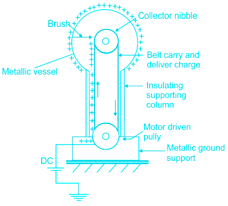
In a Van de Graaff Generator the inner sphere has higher _____________ than the outer sphere.
Solution
CONCEPT:
Van de Graaff Generator:
- It is a machine that can build up high voltages of the order of a few million volts.
- The resulting large electric fields are used to accelerate charged particles (electrons, protons, ions) to high energies needed for experiments to probe the small scale structure of matter.
The following principles are involved in the device.
- Charge on a conductor always move and stay on the outer surface.
- Pointed Corners conduct charges very effectively (corona discharge).
EXPLANATION:
- The Van de Graaff generator is an electrostatic generator, which is used for creating very high electric potentials at low current levels.
- It has a large conducting shell (of a few meters diameter) with a uniformly distributed charge over it.
- A small sphere is placed inside the conducting shell and has less charge than the shell. But the potential at the inner sphere will always be high.
- Thus, the small charge flows from high potential to low potential on the conducting shell, when connected with wire and thus keeps on building the potential on the outer shell.
- Hence option 1 is correct among all
-
Question 33
5 / -1
When a diode is reverse biased then the barrier height ____________________________.
Solution
Concept:
Reversed Bias:
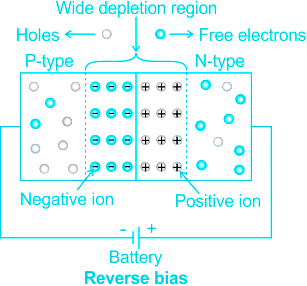
1) When reverse biased, more charge carriers are depleted, resulting in the widening of the depletion region. (Statement I is correct)
2) This increases the opposing electric field for the diffusion carriers and does not allow them to cross the junction, offering a high resistance.
3) If the reverse voltage increases beyond a certain level, the junction breakdown happens.
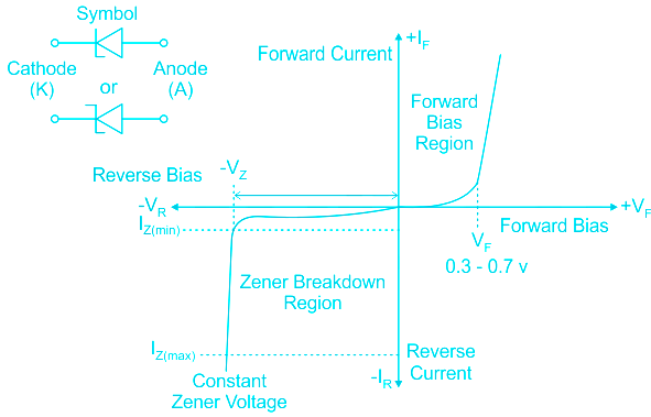
The VI characteristic of a p-n junction diode:
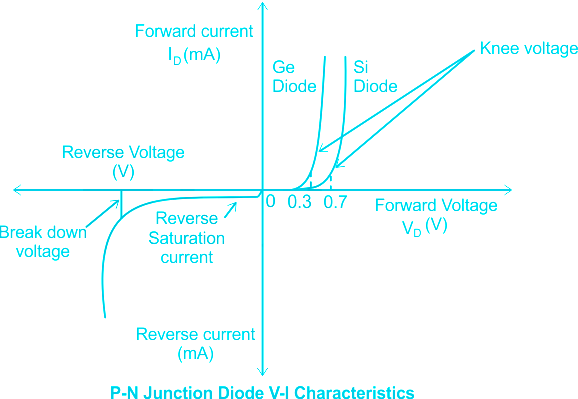
Explanation:
From the above explanation, we can see that, in reverse bias depletion region for a PN junction diode will increase, and because of this barrier height increases.
This increases the gap between conduction and valence band and thus current can't flow in reverse bias
Hence when a diode is reverse biased then the barrier height increases and the depletion region widens
-
Question 34
5 / -1
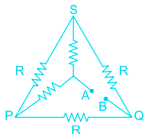
In the circuit, the equivalent resistance between A and B is (Each resistance given in the diagram is R) :
Solution
CONCEPT:
- Equivalent resistance: It shows where the aggregate resistance connected either in parallel or series is calculated.
- Essentially, the circuit is designed either in Series or Parallel.
- Electrical resistance shows how much energy one needs when you move the charges/current through your devices.
Formula for resistors connected in series / parallel:
- R = R1 + R2 + R3........(Series)
- 1/R = 1/R1 + 1/R2 + 1/R3 ......(Parallel)
EXPLANATION:
Given that,
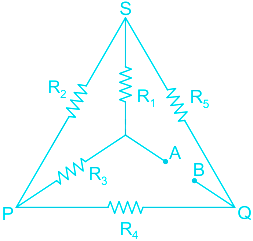
Value of all resistance is R and hence R1 = R2 = R3 = R4 = R5 = R
Identify the Junction points Between A and B and redraw the circuit.
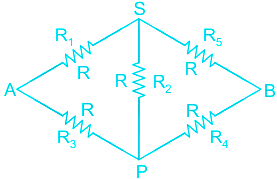
Clearly, we can see R2 is forming a Wheatstone bridge.
R1 / R3 = R / R = 1
R5 / R4 = R /R = 1
So, R1 /R3 = R5 / R4 So, it is a balanced Wheatstone bridge and hence no current will be in the PS branch.
R1 and R5 are in series equivalent = R + R = 2R
and R3 and R4 are in series, equivalent = R + R = 2R
Both are in parallel
So,
Req =(2R)2 / 2R +2R = R
So, the equivalent resistance is R
-
Question 35
5 / -1
Which of these v-I plots, is ohmic -
Solution
The plot which show Ohmic Law is
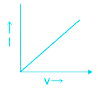
Concept:
- Ohms Law: The potential difference applied across a conductor is directly proportional to the current passing through the conductor at a constant temperature.
- V = IR
- V is the potential difference, I is current, R is resistance.
- Resistance: It is the property of the conductor which resists the flow of current across it.
Explanation:
- So, there is a linear relationship between potential difference and current.
- The graph between two quantities, if there is a linear relationship, is a straight Line.
- Therefore, the VI plot will be straight Line according to Ohms Law.
Additional Information
Ohms Law is not valid in the case of diode and transistors. We will not get straight line between V and I.
-
Question 36
5 / -1
The type of mirror used in the head lamps of cars is the:-
Solution
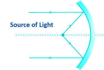
The correct answer is spherical concave mirror.
Key Points
- Concave mirrors are spherical mirrors that curve inward like a spoon.
- They create the illusion of largeness.
- For a diverging or concave mirror, the focal length is always negative.
- Concave Mirror used for Shaving mirrors, Ophthalmoscope, Astronomical telescopes, Solar furnaces, etc.
- A concave mirror is used for this purpose because it produces a parallel beam of light when the light source is present at its principle focus.
- The headlight is present at focus and after reflection, it gives a parallel ray of light on the road.
Important Points
Plane Mirror | - These are flat mirrors that reflect images in their normal proportions, reversed from left to right.
- Use looking glass, solar cookers, periscope, kaleidoscope, etc.
|
Convex Mirror | - Convex mirrors are also spherical mirrors. They bulge out and distort the reflected image, making it smaller.
- The focal length of a convex mirror is Positive.
- Use Vehicle mirrors, Magnifying glasses, Street light reflectors, etc.
|
-
Question 37
5 / -1
In Oersted's experiment, which type of electric source is used?
Solution
CONCEPT:
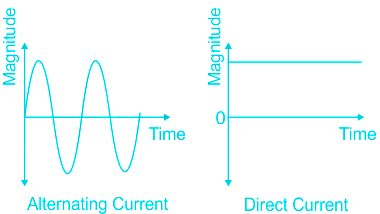
- Alternating Current (AC): Alternating current is an electric current that periodically reverses direction.
- Direct Current (DC): Direct current is the unidirectional flow of an electric charge.
- Oersted's experiment: Oersted’s conducted experiments related to electricity and magnetism.
- The compass needle showed deflection when it was placed nearby the current-carrying wire.
- This shows that the magnetic field produced by a current-carrying wire.
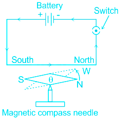
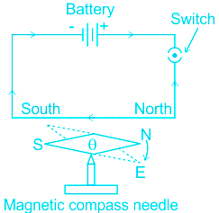
EXPLANATION:
- The deflection of the compass needle, whenever there is current in the wire shows that a current-carrying wire produces a magnetic field around it.
- The AC is pulsating in nature so the field generated is also pulsating in nature, so it was not used for this experiment.
- So, In Oersted's experiment, DC source is used, hence option 2 will be correct.
-
Question 38
5 / -1
Excitation energy of a hydrogen like ion in its first excitation state is 40.8 eV. Energy needed to remove the electron from the ion ground state is _____
Solution
CONCEPT:
- Bohr model: In 1913, Niels Bohr gave the Bohr's atom model which retained essential features of Rutherford's model and at the same time took into account its drawbacks.
- The electrons revolve around the nucleus in circular orbits which is called the stationary orbit.
- According to the Bohr's atom model, the electrons of an atom revolve around the nucleus only in those orbits in which the angular momentum of the electron is an integral multiple of h /2π.
- By absorbing energy the electrons are able to jump from lower energy(Ei) level to higher energy level (Ef) and vice versa.
- The energy of emitted radiation is given by
\(h\upsilon =E_F -E_i\)
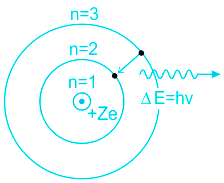
- The energy of electrons in any orbit is given by:
\(E_n=~-13.6~\frac{{{Z}^{2}}}{{{n}^{2}}}\,eV\)
Where n is the principal quantum number and Z is the atomic number.
EXPLANATION:
- The energy of electrons in an orbit is given by:
\(E_n=~-13.6~\frac{{{Z}^{2}}}{{{n}^{2}}}\,eV\)
- The energy of the ground state is given by
\(E_1=-13.6~\frac{{{Z}^{2}}}{{{1}^{2}}}\,eV =-13.6 Z^{2} eV\)
- The energy of the first excited state is given by
\(E_2=-13.6~\frac{{{Z}^{2}}}{{{2}^{2}}}\,eV = -13.6~\frac{{{Z}^{2}}}{{4}}\,eV=-3.4Z^2eV\)
- The energy required for excitation is given by
⇒ E = E2 - E1 = -3.4 Z2 - (-13.6 Z2) = 10.2 Z2 eV
- The energy required to remove an electron from the ground state will be
⇒ E1 = -13.6Z2
Substituting the value of Z2 = 4 in equation 2
⇒ E1 = -13.6 × 4 = -54.4eV
- Hence option 1 is the answer.
-
Question 39
5 / -1
A charge particle of charge q is placed at a point. Find the magnitude of electric field at a distance of 1 m from the charge particle if the space is filled with a dielectric of dielectric constant 1.5.
Solution
CONCEPT:
- Electric field: It is defined as a point in space at which an electric charge would experience a force.
- Electric field intensity can be represented in both magnitude and direction and hence it is a vector quantity.
The electric field intensity at a point due to a point charge is given by:
\(E = \frac{q}{{4\;\pi \;{\epsilon_0}{r^{2\;}}}}\) Where ϵ0 is permittivity of free space, q is charge of the point charge and r is distance from the point charge.
When a dielectric medium is given then electric field is given by:
\(E = \frac{q}{{4\;\pi \;k\;{\epsilon_0}{r^{2\;}}}}\) Where k is dielectric constant of the medium
EXPLANATION:
Given that: Dielectric constant (k) = 1.5
Distance (r) = 1 m
\(Electric\;field\;\left( E \right) = \frac{q}{{4\;\pi \;k\;{\epsilon_0}{r^{2\;}}}} = \frac{q}{{4\;\pi \; \times 1.5 \times \;{\epsilon_0} \times {1^{2\;}}}} = \frac{q}{{6\;\pi \;{\epsilon_0}}}\)
-
Question 40
5 / -1
Two charges +q and -q each of magnitude 6.0 × 10⁻⁶ C forms a dipole. The separation between the charges is 4 × 10⁻¹⁰ m. If this dipole is placed in a uniform electric field E = 3.0 × 10² NC-1 at an angle of 30° with the field then calculate the value of torque on the dipole?
Solution
CONCEPT:
- Electric dipole: When two equal and opposite charges are separated by a small distance then this combination of charges is called an electric dipole.
- The multiplication of charge and the distance between them is called as electric dipole moment.
Dipole moment (P) = q × d
Where q is charge and d is the distance between two charged particles.
Torque on electric dipole:
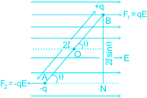
∴ τ = force × arms of couple
τ = F × 2asinθ = (qE) × 2asinθ
τ = (q × 2a)E sinθ \(\vec{τ }=\vec{p}× ~\vec{E}\)
τ = pE sinθ
\(\vec{τ }=\vec{p}× ~\vec{E}\)
CALCULATION:
Given that:
q = 6.0 × 10⁻⁶ C ; d = 4 × 10⁻¹⁰ m, E = 3.0 × 10² NC-1 and θ = 30°
The dipole moment is given by:
p = q × d = (6.0 × 10⁻⁶ C) × (4.0 × 10⁻¹⁰ m) = 24 × 10-16 Cm
Torque τ = pE sinθ
τ = (24 × 10-16 Cm) × (3.0 × 10² NC-1) sin30° = \(\frac{72}{2} × 10^{-14} Nm\)
τ = 36 × 10-14 Nm
Additional Information
- if a dipole is placed in a non-uniform electric field, the force on the charges -q and +q will be unequal.
- Such as the electric field will not only tend to rotate but also displace the dipole in the direction of the field.
-
Question 41
5 / -1
If the intensity and frequency of incident light is doubled then :
Solution
The correct answer is option 2) i.e. the kinetic energy of the emitted electron will be increased and the photoelectric current will be 2 times.
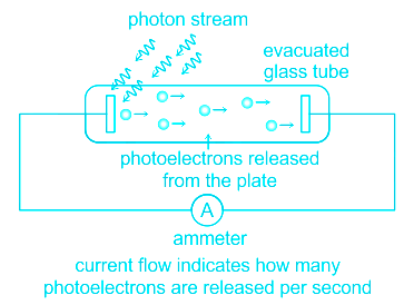
CONCEPT:
- Photoelectric effect: The photoelectric effect is a phenomenon where electrons are ejected from a metal surface when the light of sufficient frequency is incident on it.
- Einstein suggested that light behaved like a particle and that each particle of light had energy called the photon.
- When a photon falls on the metal surface, the photon’s energy is transferred to the electron.
- Some part of the energy gets utilized in removing the electron from the metal surface, and the remaining goes into giving kinetic energy for the ejected electron.
Therefore, the total energy of photon = energy utilized to eject an electron + maximum kinetic energy of the electron.
The energy of a photon is given by the equation:
\(E =hν\). Where ν is the frequency of incident light and h is the Planck's constant.
Where E is the energy of the photon, W is the minimum energy required to emit an electron, and KE is the maximum kinetic energy achieved by the ejected electron.
EXPLANATION:
- The intensity of light refers to the amount of photon energy per unit area.
- So, the greater the intensity of light more will be the number of photons, and as a result, more will be the number of ejected electrons. More electrons constitute more photocurrent.
- So if the intensity is doubled, the photocurrent also gets doubled.
- The photocurrent is independent of the frequency of incident light.
- The energy of a photon is directly proportional to the frequency of incident light. So if the frequency is doubled, The energy is also doubled. Hence, more amount of kinetic energy is available for the emitted electrons.
∴ the kinetic energy of the emitted electron will be increased and the photoelectric current will be 2 times.
-
Question 42
5 / -1
Which decay process does \({_zX^A} \longrightarrow {_{z-1}Y^A} + {_{1}e^0} + {\nu}\) represents
Solution
Content:
Beta Decay: Beta decay is a process in which either a neutron is converted into a proton (β− decay) or a proton is converted into a neutron (β+ decay). During β− decay, an electron and a new particle named antineutrino are created and emitted from the nucleus,
\(n \rightarrow p+e+\bar \nu\)
During β+ decay, a positron and a neutrino are created and emitted from the nucleus,
\(p \rightarrow n + e^+ + \nu\)
β− decay: \(_Z X^A \rightarrow _{Z+1}Y^A +e +\bar \nu\)
β+ decay: \(_Z X^A \rightarrow _{Z-1}Y^A +e^+ + \nu\)
Before the discovery of neutrino or anti-neutrino, Beta decay was assumed to take place by the release of two particles, either proton, and electron or neutron and positron depending upon the type of beta decay. So the expected energy distribution was discrete distribution. But a continuous energy distribution was observed as shown below.
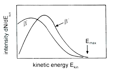
To explain this continuous energy spectrum, Pauli suggested that the continuum spectra might be due to one more “invisible” light neutral particle (later to be named neutrino and antineutrino) involved in the β-decay.
Explanation:
\({_zX^A} \longrightarrow {_{z-1}Y^A} + {_{1}e^0} + {\nu}\)
In this reaction a positron (1e0) is being emitted along with a neutrino. Hence, this reaction represents a β+ decay
The correct answer is option (3)
-
Question 43
5 / -1
How much magnification can be obtained at near point 25 cm by using a convex lens of focal length 10 cm?
Solution
CONCEPT:
- Converging lens: A lens in which light rays enter into it parallel to its axis and converge at a single point on the opposite side.
- Focal length: When light passes through a lens, the measure of how strongly the system converges or diverges the light.
- the focal length is the inverse of the system's optical power.
- Magnification: In a convex lens, the magnification is the ratio of the height of the image to the height of the object.
For near point D, magnification of the convex lens is given by
\(m = 1+\frac{D}{f}\)
where m is magnificent, D is the near point, and f is focal length of the convex lens.
CALCULATION:
Given that D = 25 cm and f = 10 cm.
magnification \(m = 1+\frac{D}{f}\)
\(m = 1+\frac{25}{10}\)
m = 3.5
So the correct answer is option 3.
-
Question 44
5 / -1
If the radius of the potentiometer wire is doubled then effect on null point
Solution
CONCEPT:
Potentiometer:
- A potentiometer is a device mainly used to measure emf of a given cell and to compare emf’s of cells.
- It is also used to measure the internal resistance of a given cell.
- If V = E then no current will flow in the galvanometer circuit this condition to known as null deflection position, length l is known as balancing length.
In balanced condition E = kl or
\(E = \left( {\frac{e}{{R + {R_h} + r}}} \right)\frac{R}{L}l\)
Where Rh = Variable resistance which controls the current through the wire AB, E =emf of the cell, L = length of the potentiometer wire, l = balancing length and R = Resistance of potentiometer wire.
EXPLANATION:
- In the Balance condition emf of the battery is equal to the potential drop across potentiometer wire.
- From above it clear that emf of the battery depends on the resistance of the potentiometer wire.
- If the radius of the potentiometer wire is doubled, then the resistance of the potentiometer wire will decrease as resistance is inversely proportional to the area of the wire.
- Therefore, if the radius of the potentiometer wire is doubled then the null point will decrease.
-
Question 45
5 / -1
How eddy current can be produced in a bulk piece of conducting material?
Solution
CONCEPT:
- Eddy Current: When a changing magnetic flux is applied to a bulk piece of conducting material then circulating currents is called eddy currents are induced in the material.
- Because the resistance of the bulk conductor is usually low, eddy currents often have large magnitudes and heat the conductor.
EXPLANATION:
- Eddy currents are the currents induced in solid metallic masses when magnetic flux threading through them changes.
- Eddy current is also known as“Focault current”.
- Eddy current also opposes the change in magnetic flux, so there is given by Lenz’s law.
-
Question 46
5 / -1
Which of the following modes is used for propagation of very high frequencies?
Solution
Space wave propagation is defined as the radio waves that occur within 20km of the atmosphere.
The waves which travel in a straight line between the transmitting antenna and receiving antenna are known as space wave.
The radio waves in this propagation can propagate either directly or after reflection from the ground or in the troposphere.
It is generally used for Line-of-Sight communication and satellite communication. It is mostly used for signals having a frequency in the Ultra high-frequency range(UHF).
Important Points
- Ground Wave propagation is a method of radio wave propagation that uses the area between the surface of the earth and the ionosphere for transmission.
- Longitudinal waves are waves in which the displacement of the medium is in the same direction as, or the opposite direction to, the direction of propagation of the wave.
-
Question 47
5 / -1
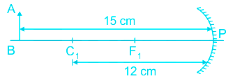
Refer to the following diagram to calculate how far (in cm) will the image be formed from the mirror. AB is the object.
Solution
CONCEPT:
Concave mirror: The mirror in which the rays converge after falling on it is known as the concave mirror.
- Concave mirrors are also known as a converging mirror.
- The focal length of a concave mirror is negative according to the sign convention.
Mirror Formula: The following formula is known as the mirror formula:
\(\frac{1}{f}=\frac{1}{u}+\frac{1}{v}\)
where f is focal length v is the distance of the image from the mirror, and u is the distance of the object from the mirror.
- Focal length: When light reflects from the mirror, the measure of how strongly the system converges or diverges the light is called focal length.
- The focal length is the inverse of the system's optical power.
For mirrors, the focal length is calculated by:
f = -R/2
where R is the radius of the curvature of the mirror.
CALCULATION:
Given that u = -15 cm and R = 12 cm
f = -R/2 = -6 cm
Mirror formula
\(\frac{1}{f}=\frac{1}{u}+\frac{1}{v}\)
\(\frac{1}{-6}=\frac{1}{v}+\frac{1}{-15}\)
v = -10 cm
So the correct answer is option 1.
-
Question 48
5 / -1
A DC voltmeter is capable of measuring a maximum of 300 volts. If it is used to measure the voltage across a device operating at 220 volt AC supply, the reading of the voltmeter will be
Solution
CONCEPT:
- Voltmeter: The device that is used to measure the electrical potential difference between two points in an electric circuit is called a voltmeter.
- The voltmeter is connected in parallel with the circuit to measure the same voltage drop occurs across it.
Based on the measurement, Voltmeter is of two types:
- DC Voltmeter
- AC Voltmeter
- To measure DC voltage, a DC voltmeter is used.
- To measure AC voltage, an AC voltmeter or hot wire voltmeter is used.
EXPLANATION:
- DC voltmeter can not measure AC voltages.
- When used in AC circuits, DC Voltmeter gives zero reading because the average value of alternating voltage over a full cycle is zero.
- So, the reading of the voltmeter will be 0 volts, as a DC voltmeter cannot be used for measuring AC potential difference as it is current direction oriented.

- To measure AC, the heating effect of the current is used because the heating effect does not depend on the direction of the flow of current.
- The hot wire Voltmeter or AC voltmeter works in the principle of heating effect.
- It measures the RMS value of voltage in AC.
-
Question 49
5 / -1
Vinod is running in front of a plane mirror with speed 4 m /s. By what speed Vinod is being approached by his image?
Solution
Concept:
Image formation by Plane mirror
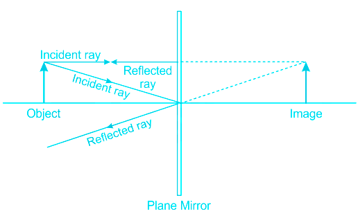
- The plane mirror always forms a virtual image of a real object. The virtual images can’t be formed on a screen.
- The size of the image formed by a plane mirror is equal to the size of the object.
- The distance between object and mirror is the same as the distance between the mirror and the image.
Simple Concept of Relative speed
- When two bodies are moving in opposite directions, their relative speed is the sum of their individual speeds
- On the other hand, when two bodies are moving in the same direction, their relative speed is the difference of their individual speeds.
Explanation:
When Vinod is running in front of the plane mirror, with a speed of 4 m / s, his image is running in the opposite direction.
The relative speed is added in that case.
So, the net relative speed will be added.
V = 4 m / s + 4 m / s = 8 m / s
So, with this speed, of 8 m / s the image is approaching VInod.
-
Question 50
5 / -1
Alternating current cannot be measured by DC ammeter because:
Solution
CONCEPT:
Mean value:
- The average of all the instantaneous values of alternating currents over one complete cycle is called the mean value.
- The mean value of the alternating current is zero.
EXPLANATION:
- The DC ammeter measures the mean value of current and the mean value of the AC current is zero, so we cannot measure the AC current by the DC ammeter.
- Hence, option 2 is correct.
Important Points
Peak value:
- The maximum value attained by an alternating current during one cycle is called its Peak value.
- It is denoted by Io.
RMS value:
- It is that steady current which, when flows through a resistor of known resistance for a given period of time than as a result the same quantity of heat is produced by the alternating current when flows through the same resistor for the same period of time is called R.M.S or effective value of the alternating current.
- The RMS value of current is given as,
\(\Rightarrow I_{rms}=\frac{I_{o}}{\sqrt{2}}\)


 ×
×

 Sign in
 Profile
 Signout


