Self Studies
Selfstudy
Selfstudy

Physics Mock Test - 6

Result Self Studies

Physics Mock Test - 6
  • Score

    -

    out of -
  • Rank

    -

    out of -
TIME Taken - -
Self Studies

SHARING IS CARING

If our Website helped you a little, then kindly spread our voice using Social Networks. Spread our word to your readers, friends, teachers, students & all those close ones who deserve to know what you know now.

Self Studies Self Studies
Weekly Quiz Competition
  • Question 1
    5 / -1
    Rain drops are spherical in shape because of - 
    Solution

    The correct answer is surface tension of water.

    Key Points

    • Raindrops start to form in a roughly spherical structure due to the surface tension of water.
      • This surface tension is the "skin" of a body of water that makes the molecules stick together.
      • The cause is the weak hydrogen bonds that occur between water molecules. On smaller raindrops, the surface tension is stronger than in larger drops. The reason is the flow of air around the drop.
    • As the raindrop falls, it loses that rounded shape. The raindrop becomes more like the top half of a hamburger bun. Flattened on the bottom and with a curved dome top, raindrops are anything but the classic tear shape. The reason is due to their speed falling through the atmosphere.
    • Airflow at the bottom of the water drop is greater than the airflow at the top.
    • At the top, small air circulation disturbances create less air pressure.
    • The surface tension at the top allows the raindrop to remain more spherical while the bottom gets more flattened out.

    Additional Information

    • Surface tension: The property by virtue of which liquid tries to minimize its free surface area is called surface tension.
      • In a spherical shape, the surface area is minimum and for this reason, the raindrops are spherical.
      • Surface tension is measured as the force acting per unit length of an imaginary line drawn on the liquid surface.
    • \(Surface\;tension = \frac{{Force}}{{length}}\)
    • Due to the surface tension, a liquid drop tends to assume a spherical shape to minimize the surface area. 
  • Question 2
    5 / -1
    In nuclear reaction \({_{90}^{237}Th} \longrightarrow {_{91}^{237}Pa} + X\) : Here particle X is
    Solution

    CONCEPT:

    • Radioactive decay: When the n/p ratio of an atomic nucleus is high enough to make it unstable, it decays.
    • Radioactive decay mainly emits α- particles, β- particles, and gamma rays.
    • What happens when an α- particle is emitted:
      • An alpha particle is identical to a helium nucleus, is made up of two protons and two neutrons bound together.
      • The original atom is changed into a different element.
      • Its mass number or atomic mass decreases by four and its atomic number by two.
      • Mass number A to A-4 and atomic number Z to Z-2.

    ZXA —→ Z-2XA-4 + 2α4

    • What happens when a β- particle is emitted:
      • The electron leaves the atom as a beta particle but the proton stays in the nucleus.
      • The original atom is changed into a different element.
      • The mass number or atomic mass stays the same but the atomic number increases by 1.
      • The mass number will remain the same A and atomic number Z to Z+1. 

    ZXA —→ Z+1XA + -1β0

    • What happens when γ- rays are emitted:
      • Gamma decay is the emission of energy in the form of photons from the nucleus of the atom.
      • Gamma rays are electromagnetic waves.
      • They are pure energy. They have no mass or atomic number.

    CALCULATION:

    • Given equation is \({_{90}^{237}Th} \longrightarrow {_{91}^{237}Pa} + X\)
    • Given that elements Th and Pa have the same mass number is A.
      • There is an emission of no α- particles
    • Given that elements Pa has an atomic number (91) one more than that of Th (90)
      • There is an emission of one β- particles
    • So the X particle is a β- particle.

    \({_{90}^{237}Th} \longrightarrow {_{91}^{237}Pa} + _{-1}\beta^0\)

    So the correct answer is option 4.

  • Question 3
    5 / -1

    Junction transistors are of bipolar type because ________

    Solution

    In junction transistors, the current conduction is due to the flow of both electrons and holes hence they are known as bipolar devices.

    A diode is also a bipolar device while JFETs and MOSFETs are unipolar devices.


  • Question 4
    5 / -1
    The process of superimposing signal frequency ( i.e. audio wave) on the carrier wave is known as 
    Solution

    CONCEPT:

    • Modulation is the process in which some characteristics, usually an amplitude, frequency or phase angle of a high-frequency carrier wave is varied in accordance with the instantaneous value of low-frequency information signal called modulating signal.

    EXPLANATION:

    • Low-frequency wave cannot be transmitted to long distances. So, low-frequency information signal is superimposed on a high-frequency wave, which acts as a carrier of the information. Thus option 3 is correct.
    • A transmitter is a device which process a message signal into a form suitable for transmission and then transmits it to the receiving end through a transmission medium.
    • A receiver is a device that recovers the original message signal from the signal received at the output of the communication channel.
  • Question 5
    5 / -1

    The mutual inductance between two coils is 1.25 henry. If the current in the primary coil changes at the rate of 80 amperes/second, then induced e.m.f. in the secondary coil is 

    Solution

    Concept:

    Mutual Induction: Whenever the current passing through a coil or circuit changes, the magnetic flux linked with a neighboring coil or circuit will also change.

    Hence, an emf will be induced in the neighboring coil or circuit. This phenomenon is called ‘mutual induction’.

    Mutual induction between the two coils of area A, number of turns N1 and N2 with the length of secondary or primary l is given by:

    \(M = \frac{{{\mu _{o\;{N_1}{N_2}A}}}}{l}\)

    Emf induced in the coil is given by:

    \(e=M\frac{{di}}{{dt}}\)

    Calculation:

    Given that, M = 1.25 H, dI/dt = 80 amp/sec

    Emf induced in the coil is given by,

    \(e=M\frac{{di}}{{dt}}\)

    e = 1.25 × 80

    = 100 Volt.

  • Question 6
    5 / -1

    Find value of R in the following circuit diagram. 

    Solution

    Concept:

    • Equivalent Resistance: Equivalent Resistance between two Points is the ratio of Potential Difference between them and the amount of current passing through them.
    • Equivalent Resistance can also be defined as the resistance of the resistor which will replace all the resistors between two points and will draw the same current between these two points as it was flowing Earlier. 
      • Symmetry: A group of the same set of resistors connected in series with a similar group then we can say, there is symmetry in Circuit. 

    Different Types of Connections are Series Connection and Parallel Connection.

    Series ConnectionParallel Connection
    Resistors are connected in such a way that the same current is passing across them.Resistors are connected in such a way that potential difference is the same Across them.

    Equivalent Resistance of n resistors connected in series is given as 

    R = R1 + R2 + R3 .....R


    Equivalent Resistance of n resistors Connected in Parallel is given as 

    \(\frac{1}{R} = \frac{1}{R_{1}} +\frac{1}{R_{2}} + \frac{1}{R_{3}}.....+ \frac{1}{R_{n}}\)

    Circuit Diagram:

    Circuit Diagram: 


    Ohms Law

    • Ohms Law: At constant temperature, a potential difference is the product of current and resistance.

    ​V = IR

    V is the potential difference, I is current, R is resistance

    Calculation:

    Here, two resistors are in Parallel, with each has resistance R

    The equivalent resistance is 

    \(\frac{1}{R_e} = \frac{1}{R} +\frac{1}{R} \)

    \(\implies \frac{1}{R_e} = \frac{2}{R}\)

    \(\implies R_e = \frac{R}{2}\)

    Given, Potential difference V = 12 V

    Current I = 100 m A

    Re = V / I

    ⇒ Re = 12 V / 100 mA = 120 Ω 

    \(\implies R_e = \frac{R}{2} = 120 \Omega \)

    ⇒ R = 240 Ω

    So, the correct option is 240 Ω.

  • Question 7
    5 / -1
    The function of LC tuned circuit used in a receiver is used –
    Solution

    CONCEPT:

    • LC Circuit: The circuit containing both an inductor (L) and a capacitor (C) can oscillate without a source of emf by shifting the energy stored in the circuit between the electric and magnetic fields is called LC circuit.
    • The tuned circuit has a very high impedance at its resonant frequency

    EXPLANATION:

    • The function of an LC tuned circuit is to tune a radio to a particular station. So option 3 is correct.
    • The LC circuits are set at resonance for that particular carrier frequency.
  • Question 8
    5 / -1
    An observer looks at a tree of height 15 m. with a telescope of magnifying power 10. To him the tree appears
    Solution

     The correct answer is 10 times nearer.

    Key Points

    • The angle subtended at the eye becomes 10times larger, this happens and the tree appears 10 times nearer.

    Additional Information 

    • Magnifying power is how much larger a given lens can make an image appear.
    • This is a direct relationship between the focal length of the lens and the least distance of distinct vision.
    • The magnifying power of the telescope is the ratio of the angle subtended at the eye by the image to the angle subtended at the unaided eye by the object
  • Question 9
    5 / -1
    The force acting between two protons in a nucleus is:
    Solution

    CONCEPT:

    • Strong nuclear force: The strong attractive force which binds together the protons and neutrons in a nucleus is called a strong nuclear force.
    • This force cannot be an electrostatic force because positively charged protons strongly repel each other at such a small separation of the order 10-15 m.
    • This strong nuclear force is the strongest of all the fundamental forces, about 100 times stronger than the electromagnetic force.

    Important properties of the strong nuclear force:

    1. It is the strongest interaction known in nature, which is about 1038 times stronger than the gravitational force.
    2. It is a short-range force that operates only over the size of the nucleus (= 10-15 m).
    3. It is basically an attractive force but becomes repulsive when the distance between the nucleons becomes less than 0.5 fermis (1 fermi =10-15 m).
    4. It varies inversely with some higher power (>2) of distance.
    5. It is a non-central and non-conservative force

    EXPLANATION:

    • From the above, it is clear that the force acting between two protons in a nucleus is a strong nuclear force. Therefore option 2 is correct.

    Additional Information

    • Nuclear forces don't depend on the charge as it works on neutrons (which have no charge) and protons.
    • Nuclear forces are independent of charge i.e., the nuclear force between two protons is the same as that between two neutrons or between a proton and a neutron
  • Question 10
    5 / -1
    Which waves are produced by using a magnetron valve?
    Solution

    CONCEPT:

    • Electromagnetic spectrum: It is a collection of a range of different waves in sequential order from radio to gamma electromagnetic waves.

    Frequency (ν) = speed of light (c)/wavelength (λ)

    • Radio waves: The lowest frequency portion comes in radio waves generally, has wavelengths range between 1 mm to 100 km or frequencies between 300 GHz to 3 kHz.
      • There are several subcategories in between these waves like AM and FM radio. It is used for communication such as television and radio.
    • Microwaves: The part of the electromagnetic spectrum having the frequency more than that of radio waves and less than that of infrared waves are called microwaves.
      • It is used for cooking food and for satellite communications.
    • Infrared Waves - It is used by electrical heaters, cookers for cooking food, and by infrared cameras that detect people in the dark.
    • Gamma Rays - It is used in medicine (radiotherapy), industry (sterilization and disinfection), and the nuclear industry.
      • Gamma Rays have the minimum wavelength and maximum frequency.

    Explanation:

    • magnetron valve is used to produce microwaves.
    • Magnetron works as a self-excited microwave oscillator and is a high-powered vacuum tube.
    • The combined action of a magnetic field that is externally applied and the electric field between its electrodes forms the basis of the operation of the magnetron.
  • Question 11
    5 / -1
    Two long wires A and B are placed parallel to each other. If the ratio of current in the wire A to wire B is 1 : 2, then the ratio of the force per unit length on wire A to wire B is:
    Solution

    CONCEPT:

    The force between two parallel currents:

    • We know that there exists a magnetic field due to a conductor carrying a current.
    • And an external magnetic field exerts a force on a current-carrying conductor.
    • Therefore we can say that when two current-carrying conductors placed nearby each other will exert (magnetic) forces on each other.
    • In the period 1820-25, Ampere studied the nature of this magnetic force and its dependence on the magnitude of the current, on the shape and size of the conductors, as well as, the distances between the conductors.
    • Let two long parallel conductors a and b separated by a distance d and carrying (parallel) currents Ia and Ib respectively.
    • The magnitude of the magnetic field intensity due to wire a, on the wire b is,

    \(⇒ B_a=\frac{\mu_oI_a}{2\pi d}\)

    • The magnitude of the magnetic field intensity due to wire b, on the wire a is,

    \(⇒ B_b=\frac{\mu_oI_b}{2\pi d}\)

    • The conductors 'a' and ‘b’ carrying a current Ia and Ib respectively will experience sideway forces due to magnetic field Bb and Ba respectively.

    CALCULATION:

    Given \(\frac{I_a}{I_b}=\frac{1}{2}\)

    If two current-carrying long wires A and B are separated by a very small distance and placed parallel to each other. Then the force per unit length on wire A and wire B is given as,

    \(\Rightarrow f_{ab}=f_{ba}=\frac{\mu_o I_aI_b}{2\pi d}\)     -----(1)

    Where Ia = current in the wire A, Ib = current in the wire B, and d = distance between the wires

    By equation 1 it is clear that whatever be the current in any wire, the force per unit length on both the wires will remain equal.

    • So the ratio of the force per unit length on wire A to wire B will be,

    \(\Rightarrow \frac{f_{ab}}{f_{ba}}=\frac{1}{1}\)

    • Hence, option 1 is correct.

    Additional Information

    • The magnitude of the force on the segment L of the wire 'a' due to magnetic field Bb is given as,

    \(⇒ F_{ab}=\frac{\mu_o I_aI_b}{2\pi d}L\)

    • The magnitude of the force on the segment L of the wire 'b' due to magnetic field Ba is given as,

    \(⇒ F_{ba}=\frac{\mu_o I_aI_b}{2\pi d}L\)

    1. The magnitude of the force per unit length on wire a and wire b is given as,

    \(⇒ f_{ab}=f_{ba}=\frac{\mu_o I_aI_b}{2\pi d}\)

    Important Points

    • When the current flows in the same direction in the two parallel wires then both wires attract each other and if the current flows in the opposite direction in the two parallel wires then both wires repel each other.
  • Question 12
    5 / -1

    A charged conductor is placed in an external electric field. The electric field inside the conductor is

    Solution

    CONCEPT:

    Conductors:

    • Conductors contain mobile charge carriers. In metallic conductors, these charge carriers are electrons. 
    • In an external electric field, they drift against the direction of the field.
    • In electrolytic conductors, the charge carriers are both positive and negative ions.

    Important results regarding electrostatics of conductors:

    1. Inside a conductor, the electrostatic field is zero.
    2. At the surface of a charged conductor, the electrostatic field must be normal to the surface at every point
    3. The interior of a conductor can have no excess charge
    4. The electrostatic potential is constant throughout the volume of the conductor and has the same value (as inside) on its surface.
    5. The electric field at the surface of a charged conductor is \( E=\frac{\sigma}{\varepsilon_{0}} ̂{n}\)
    6. Electrostatic shielding.

    EXPLANATION:

    • A charged conductor is placed in an external electric field.
    • The charge is distributed on the surface of the conductor.
    • The free electrons move opposite the direction of the external electric field.
    • Thus more charges are induced on the surface of the conductor due to this movement of free electrons.
    • The free electrons move until the force due to the external field is negated completely due to the force by induced charges.
    • At this point, the net force on a free electron inside the conductor is zero.
    • Therefore the net electric field inside the conductor is zero.
    • inside the conductor.​ ​Therefore option 3 is correct.

    Additional Information 

    • Inside a conductor, the electrostatic field is zero.
      • There may be an external electrostatic field. A conductor has free electrons. As long as the electric field is not zero, the free charge carriers would experience force and drift. In the static situation, the free charges have so distributed themselves that the electric field is zero everywhere inside.
    • At the surface of a charged conductor, the electrostatic field must be normal to the surface at every point. 
      • If E were not normal to the surface, it would have some non-zero components along the surface. Free charges on the surface of the conductor would then experience force and move. Therefore, E should have no tangential component.
    • The interior of a conductor can have no excess charge. 
      • A neutral conductor has equal amounts of positive and negative charges in every small volume or surface element. When the conductor is charged, the excess charge can reside only on the surface. This can be derived from Gauss' Law
    • The electrostatic potential is constant throughout the volume of the conductor and has the same value (as inside) on its surface. 
      • This follows from results 1 and 2 above. Since E = 0 inside the conductor and has no tangential component on the surface, no work is done in moving a small test charge within the conductor and on its surface. That is, there is no potential difference between any two points inside or on the surface of the conductor.
    • The electric field at the surface of a charged conductor is 
      • Where σ is the surface charge density and is a unit vector normal to the surface in the outward direction. For σ > 0, the electric field is normal to the surface outward; for σ < 0, the electric field is normal to the surface inward.
    • Electrostatic shielding.
      • Consider a conductor with a cavity, with no charges inside the cavity. A remarkable result is that the electric field inside the cavity is zero. Whatever be the size and shape of the cavity and whatever be the charge on the conductor and the external fields in which it might be placed. The electric field inside the cavity of any conductor is zero. All charges reside only on the outer surface of a conductor with a cavity.  
  • Question 13
    5 / -1

    Consider a beam of light is incident on a glass slap of refractive index 1.54 is reflected from the surface with an angle of incidence 33°. Now if the reflected ray is passed through a polaroid as shown below, in such case which of the following statement is correct?

    (Given tan 57° = 1.54)


    Solution

    CONCEPT:

    Brewster's law:

    • According to Brewster's law, the refractive index of the medium is numerically equal to the tangent angle of polarization.

    ​⇒ μ = tan θp

    Where μ = refractive index and θP = polarization angle

    • When the reflected light is completely polarised, then the angle between the reflected and the refracted light is 90°.

    Malus’ law:

    • Malus’ law states that the intensity of plane-polarized light that passes through an analyzer varies as the square of the cosine of the angle between the plane of the polarizer and the transmission axes of the analyzer.
    • When the polarized light is passed through the polaroid its intensity becomes,

    ⇒ I = Iocos2θ

    Where Io = intensity of incident polarised light

    CALCULATION:

    Given m (refractive index) = 1.54, angle of incidence i = (90 - 33) = 57° and tan 57° = 1.54

    ⇒ tan i =  tan 57°

    ⇒ tan i =  1.54

    ∴ By Brewster's law, the ray is incident at Brewster's angle so the reflected ray will be plane polarised.

    So when this ray is passed through polarises the ray will display intensity according to the law of malus

    ⇒ I = I0 cos2 θ     -----(1)

    • By equation 1 we can say that the intensity will change according to cosθ.
    • So the intensity gradually reduces to zero and then again increases.
    • Hence, option 4 is correct.

    Additional Information

    Unpolarized light:

    • A light wave that has vibrations in more than one plane is known as unpolarized light.

    Polarized light:

    • Polarized light is a light wave in which the vibrations occur in a single plane.

    Polarisation by reflection:

    • Brewster discovered that when a beam of unpolarized light is reflected from transparent medium, then at a certain angle of incidence the reflected light will be completely plane polarised.
    • The angle of incidence at which the light becomes polarised is called the angle of polarisation.
  • Question 14
    5 / -1

    A luminous object is placed at a distance of 30 cm from the convex lens of focal length 20 cm. On the other side of the lens, at what distance from the lens a convex mirror of radius of curvature 10 cm be placed in order to have an upright image of the object coincident with it -

    Solution

    Concept:

    • Lens: The transparent curved surface which is used to refract the light and make an image of any object placed in front of it is called a lens.
    • Convex lens: ​A lens having two spherical surfaces, bulging outwards is called a double convex lens (or simply convex lens).
      • It is thicker in the middle as compared to the edges.
      • Convex lenses converge light rays and hence, convex lenses are also called converging lenses.
      • It forms a virtual image when the object is placed in front of the focal point.
      • The image formed is magnified and upright.

    Lens formula is given by:

    \(\frac{1}{v} - \frac{1}{u} = \frac{1}{f}\)

    The magnification of the lens is given by:

    Magnification (m) = \(\frac {{-}{v}}{u}\)

    Where u is object distance, v is image distance and f is the focal length of the lens

    Calculation:

    Given that, u = -30 cm, f = 20 cm

    since in convex lens object is placed in front of the lens, so the value of u is negative.

    • In order to obtain the image coincident on the mirror, refraction must be formed on the centre of the curvature of a convex mirror.

    The distance from a convex lens after refraction can be calculated using the lens formula.

    The lens formula is,

    \(\frac{1}{v} - \frac{1}{u} = \frac{1}{f}\)

    \( \frac{1}{v} = \frac{1}{u} + \frac{1}{f} = \frac{1}{{ - 30}} + \frac{1}{{20}} \)

    v = 60 cm

    The image is formed at a distance of 60 cm from the lens.

    Thus convex mirror should be kept at a distance of 60 - 10 = 50 cm


  • Question 15
    5 / -1
    The magnetic flux linked with a coil in weber is given by the equation ϕ = 6t2 + 3t + 2. Then the magnitude of induced emf in the coil at t = 3 sec will be:
    Solution

    CONCEPT:

    Faraday's first law of electromagnetic induction:

    • Whenever a conductor is placed in a varying magnetic field, an electromotive force is induced.
    • If the conductor circuit is closed, a current is induced which is called induced current.

    Faraday's second law of electromagnetic induction:

    • The induced emf in a coil is equal to the rate of change of flux linked with the coil.

    \(⇒ e=-N\frac{dϕ}{dt}\)

    Where N = number of turns, dϕ = change in magnetic flux and e = induced e.m.f.

    • The negative sign says that it opposes the change in magnetic flux which is explained by Lenz law.

    CALCULATION:

    Given - ϕ = 6t2 + 3t + 2 and t = 3 sec

    • Magnetic flux linked with a coil is given as

    ⇒  ϕ = 6t2 + 3t + 2

    \(⇒ \frac{dϕ}{dt}=\frac{d}{dt}(6t^2+3t+2)\)

    \(⇒ \frac{dϕ}{dt}=12t+3\)     -----(1)

    So induced emf is given as,

    \(⇒ e=\frac{dϕ}{dt}\)

    ⇒ e = 12t +3     -----(2)

    Induced emf at t = 3 sec,

    ⇒ e = 12 × 3 +3

    ⇒ e = 39 V

    • Hence, option 1 is correct.
  • Question 16
    5 / -1
    In deriving DC equivalent circuit for an amplifier circuit we open circuit _____
    Solution

    DC analysis:

    • Find dc equivalent circuit by replacing all capacitors by open circuits and inductors by short circuits
    • Find Q-point from dc equivalent circuit by using appropriate large-signal transistor model


    AC analysis:

    • Find AC equivalent circuit by replacing all capacitors by short circuits, inductors by open circuits, dc voltage sources by ground connections and dc current sources by open circuits
    • Replace transistor by its small-signal model
    • Use small-signal ac equivalent to analyze ac characteristics of amplifier
    • Combine end results of dc and ac analysis to yield total voltages and currents in the network
  • Question 17
    5 / -1
    In Binary Algebra, A + B can be implemented by:
    Solution
    • A+B is the OR operation
    • NAND and NOR gates are universal gates and can be used to implement OR operation
    • Implementation of OR gate using NAND and NOR gates is shown

  • Question 18
    5 / -1
    Arrange metal, non- metal and semiconductor on the basis of resistance?
    Solution

    CONCEPT:

    Conductors:

    • Conductors are materials that allow current to pass through it.
    •  They have very low values of resistivity, usually in the micro-ohms per meter.
    • In conductor outer electrons of the atoms are loosely bound and free to move through the material and when an electric field is applied across it, they began to move in one direction giving rise to electric current.
    • Examples of good conductors are generally metals such as Copper, Aluminium, Silver.


    Insulators:

    • Insulators, on the other hand, are the exact opposite of conductors.
    • They are made of materials, generally, non-metals, that have very few or no “free electrons” floating about within their basic atom structure because the electrons in the outer valence shell are strongly attracted by the positively charged inner nucleus.
    • Insulators also have very high resistances and are generally not affected by normal temperature changes.
    • Examples of an insulator or non-metals are Carbon.


    Semiconductors:

    • Semiconductors materials such as silicon (Si), germanium (Ge) and gallium arsenide (GaAs), have electrical properties somewhere in the middle, between those of a “conductor” and an “insulator”.
    • They are not good conductors nor good insulators (hence their name “semi”-conductors).
    • They have very few “free electrons” because their atoms are closely grouped in a crystalline pattern called a “crystal lattice” but electrons are still able to flow, but only under special conditions.


    EXPLANATION:

    • From above it is clear that Non-metals (or insulator) have maximum resistance, then comes semiconductor and then metals (or conductor).
    • Therefore the correct order is Metal < Semiconductor < Non-metal.
  • Question 19
    5 / -1

    For the arrangement of capacitors as shown in the circuit, the effective capacitance between the points A and B is (capacitance of each capacitor is 4 μF)

    Solution

    Concept-

    • The device that stores electrical energy in an electric field is called capacitor.
    • The capacity of a capacitor to store electric charge is called capacitance.

    Combination of capacitors:


    1. Capacitor in parallel combination:

    • When two or more capacitors are connected in such a way that their ends are connected at same two points and have equal potential difference for all capacitor is called parallel combination of capacitor.

    Equivalent capacitance (Ceq) for parallel combination:

    Ceq = C1 + C2

    2.Capacitor in series combination:

    • When two or more capacitor are connected end to end and have same electric charge on each iscalled series combination of capacitor.

    Equivalent capacitance (Ceq) in series combination:

    \(\frac{1}{{{C_{eq}}}} = \frac{1}{{{C_1}}} + \frac{1}{{{C_2}}}\)

    Wheatstone bridge:


    • When 5 capacitors are connected in such a way that the ratio of two capacitors in sides are equal then the potential difference across the middle capacitor (C) is zero and we can remove that capacitorfrom the circuit.


    \(\frac{{{C_1}}}{{{C_2}}} = \frac{{{C_3}}}{{{C_4}}}\)

    Explanation-

    According to the given arrangements of the capacitors, we can rearrange as shown below:

    Here

    \(\frac{{{C_1}}}{{{C_2}}} = \frac{{{C_3}}}{{{C_4}}} = \frac{4}{4} = 1\)

    This is a Wheatstone bridge, so we will remove middle 4 μ F capacitor from the circuit.

    Now C1 is in series with C3 and C2 is in series with C4:

    \(\frac{1}{{{C_{eq}}}} = \frac{1}{{{C_1}}} + \frac{1}{{{C_3}}} = \frac{1}{4} + \frac{1}{4} = \frac{2}{4} = \frac{1}{2}\)

    Ceq = 2 μ F

    \(\frac{1}{{{C_{eq\;}}'}} = \frac{1}{{{C_2}}} + \frac{1}{{{C_4}}} = \frac{1}{4} + \frac{1}{4} = \frac{2}{4} = \frac{1}{2}\)

    Ceq‘= 2 μ F

    Now both the 2 μ F capacitors are in parallel.

    Thus equivalent capacitance (Ceq) = 2 + 2 = 4 μ F
  • Question 20
    5 / -1
    The magnetic moment (m) of a current loop = _________. ('I' is the current in the loop and 'A' is the area of the rectangular loop)
    Solution

    Concept:

    • If the circular loop is considered as a magnetic dipole, then the dipole moment is the product of current and area. But the circular loop has multiple numbers of turns.
    • Therefore, the magnitude of dipole moment = area × current × number of turns.

    i.e. m = NIA = NI (π r2)

    where, Magnetic moment of copper coil = m

    No of loops = N

    Current flowing though loop = I

    Area of coil = r

    Explanation:

    From the above explanation we can see that, magnetic moment of circular coil with N number of terms is expressed as 

    m = NIA

    Now for a sing loop the above equation can be expressed as 

    m = IA 

  • Question 21
    5 / -1
    The core of a transformer is laminated to:
    Solution

    CONCEPT:

    • Transformer: It is a device used in the power transmission of energy.
      • It works on the principle of mutual induction, where two coils are coupled, namely the primary and the secondary coil.
      • The primary coil creates a varying magnetic flux, which in turn induces an EMF on the secondary coil.
      • If the number of windings on the primary coil is greater than the secondary windings, then it is called a step-down transformer.
      • If this case is vice versa then the transformer is a step-up transformer.

    EXPLANATION:

    • Transformer cores are laminated in order to minimize eddy current loss.
    • By providing laminations, the area of each part gets reduced and hence resistance will get very high which limits the eddy current to a minimum value, and hence eddy current losses gets reduced
    • The laminations provide small gaps between the plates.
    • As it is easier for magnetic flux to flow through iron than air or coil, the stray flux or leakage flux that can cause core losses is minimized.

    The core of a transformer is laminated to reduce the power loss due to eddy current.

    Important Points

    • The efficiency of the transformer depends on how well the input power is transferred as output power.
    • Thus to increase the efficiency, the windings of the coil must be increased and magnetic flux leakage must be reduced.
  • Question 22
    5 / -1
    The center of curvature of a small aperture concave mirror is 20 cm. If the required magnification of the image is 3 times the object and the image should be straight, then where the object should be kept ahead of the mirror?
    Solution

    Concept:

    • Concave mirror: The mirror in which the rays converge after falling on it is known as the concave mirror. It has a reflecting surface curved inward. 
      • Concave mirrors are also known as converging mirrors.
      • The focal length of a concave mirror is negative according to the sign convention.
    • Magnification: In a concave mirror, magnification is the ratio of the height of the image to the height of the object.
      • When the image is real, the magnification will be negative because the real image is inverted.
      • When the image is virtual, the magnification will be positive because the virtual image is erect.

     \(m = \frac{-v}{u}\)

    • Mirror Formula: The following formula is known as the mirror formula:


    \(\frac{1}{f}=\frac{1}{u}+\frac{1}{v}\)

    f is focal length, u is object distance, v is image distance. 

    • The Center of curvature of the mirror is twice the focal length. Focal length is a point where parallel rays of light converge after reflection. 


    Sign convention in mirrors

    Calculation:

    Given, center of curvature C = 20 cm

    focal length f = C / 2 = 20 cm / 2 = 10 cm

    focal length of the concave mirror is negative, f = -10 cm

    Magnification 

    \(m = \frac{-v}{u}\)

    m = 3 (given)

    \(3= \frac{-v}{u}\)

    v = - 3 u 

    \(\frac{1}{f}=\frac{1}{u}+\frac{1}{v}\)

    \(\implies \frac{1}{-10}=\frac{1}{u}+\frac{1}{-3u}\)

    \(\implies \frac{1}{-10}=\frac{2}{3u}\)

    u = - 20 / 3 cm  = -6. 67 cm

    So, the object distance is 6.67 cm

    The object should be kept at distance 6.67 cm ahead of mirror. 

    Additional Point

    Magnification can also be produced by the concave mirror when object is between focus and center. Then the image will be real and inverted. 

  • Question 23
    5 / -1

    Which of the following option gives the correct formula for energy stored in a capacitor?

    Solution

    CONCEPT:

    • Capacitance: The ability of an electric system to store an electric charge is known as capacitance.

    The Energy stored in capacitance is given by:

    E = Q2/2C or

    E = 1/2 × C × V2

    where Q is the charge on capacitance, V is the voltage of capacitance, and C is the capacitance of it.

    EXPLANATION:

    Energy stored in a capacitor is given by both of the formulas:

    \(E= {1\over 2}CV^2\) and \(E= {Q^2\over 2C}\)

    So the correct answer is option 3.

  • Question 24
    5 / -1
    In total internal reflection when the angle of inclination is equal to the critical angle for the pair of media in contact, what will be the angle of reflection?
    Solution

    Concept:

    • According to the definition, a critical angle provides an angle of refraction of 90 degrees.
    • That means the angle of refraction will be the right angle if we get a particular incidence angle value which is expressed as (ic) and this particular incidence angle is called the critical angle.
    • The optical phenomena are effective when light is passing between two different media.
    • For example, air-water, glass-water, etc.


    Calculation:

    given that,

    • At ic = I in this case as explained above the refracted ray will graze with the surface as shown below


    Hence the angle of refraction is 90°

  • Question 25
    5 / -1
    With rise of temperature the coefficient of electrical resistance
    Solution

    Concept:

    Resistance: 

    • Resistance is a measure of the opposition to current flow in an electrical circuit.
    • It is denoted by R and SI unit is the ohm (Ω) 
    • It depends on the cross-sectional area of the conductor, the length of the conductor, and its resistivity

    Variation of resistance with temperature:

    R = R0[1 + α (T - T0)]   where

    R = conductor resistance at temperature T,  R0 = conductor resistance at a reference

    T = conductor temperature inC,  T0  = reference temperature

    Temperature coefficient of resistance (α):  It is one of the important parameters to define resistance for any material as a function of temperature.

    Thermistor:

    • Thermistors are non-linear resistors, which alter resistance characteristics with temperature.
    • The resistance of thermistors will decrease with the temperature increases. 

    Semiconductor:

    • A semiconductor is a material that behaves as an insulator at very low temperature and a conductor at room temperature.
    • The pure semiconductors and insulating material are having a negative temperature coefficient of resistance.
    • Therefore, the resistance of semiconductors and insulators decreases with rising in temperature.
    • Doping is done to alter the conductivity of semiconductor material.
    • Temperature coefficient of resistance of a doped semiconductor positive or negative depending on the level of doping.

    Tungsten wire: 

    • At high temperatures, the tungsten filament gets hot and atoms in the filament vibrate more.
    • The electrons in the current now collide more with the atoms & more energy is needed to push the current through the filament.
    • Hence, the resistance of tungsten increases with temperature.

    Explanation:

    From the above discussion, we can see that, With rising temperature the coefficient of electrical resistance

    • Decreases for the thermistor.
    • For doped semiconductor, increase or decrease depending on the amount of impurity (doping) added.
    • Increases for tungsten due to increasing the number of collision of electrons.
    • Decreases for pure semiconductor.

    Hence, option 1 will be the correct answer.

  • Question 26
    5 / -1
    AC, voltage 100 V, 50 Hz is applied to the ends of a choke of L = 2 Henry. What current will flow through it (in amperes) ?
    Solution

    Concept:

    For alternating current. the impedance of the purely inductive circuit is 

     Z = XL = 2πfL  = ω L

    Current

     \(I = \frac{V}{{iω L}}\)

    Calculation:

    Given voltage V = 100 V
    Frequency of AC Current f = 50 Hz

    Choke coil inductance L = 2 Henry

    Angular frequency ω = 2 π f = 2 π (50)

    Current

    \(I = \frac{V}{{ω L}} = \frac{100}{{2 \pi \times 50 \times 2}}\)

    \(\implies I = \frac{100}{{2 \pi \times 50 \times 2}} = \frac{1}{2 \pi }\)

    The voltage supplied is AC, the current will be AC.

    The correct option is \(\frac{1}{2 \pi} A.C\)

    Additional Information

    • Reactance: It is basically the inertia against the motion of the electrons in an electrical circuit.
    • The unit of reactance is the ohm. In an electrical circuit.

    For a purely capacitive circuit, the impedance is R = 1 / ωC

    I = V / R = V / (1 / ωc ) = V ω C

    • Impedance is the net resistance offered in an LCR AC Circuit. 
  • Question 27
    5 / -1
    The electric flux from a cube of side ‘a’ is ‘Φ’. What will be its value if the side of the cube is made ‘2a’ and the charge enclosed is made half?
    Solution

    The correct answer is option 1) i.e. Φ/2

    CONCEPT:

    Gauss's Law for electric field: It states that the total electric flux emerging out of a closed surface is directly proportional to the charge enclosed by this closed surface. It is expressed as:

    \(ϕ = \frac{q}{ϵ_0}\)

    Where ϕ is the electric flux, q is the charge enclosed in the closed surface and ϵ0 is the electric constant.

    EXPLANATION:

    Given that:

    Consider a charge 'q' placed inside a cube of side 'a'.

    The electric flux according to Gauss's law, 

    \(\Rightarrow ϕ = \frac{q}{ϵ_0}\)

    If the charge enclosed is halved, then  

    \(\Rightarrow q' =\frac{q}{2}\)

    Therefore, the new electric flux associated with this, 

    \(\Rightarrow ϕ' =\frac{q'}{\epsilon_0}= \frac{\frac{q}{2}}{ϵ_0} = \frac{1}{2}\times \frac{q}{\epsilon_0} \)

    \(\Rightarrow \phi '= \frac{1}{2} \times \phi = \frac{\phi}{2}\)


    The electric flux emerging from a closed surface is independent of the shape or dimensions of the closed surface.

  • Question 28
    5 / -1
    Which of the following obeys inverse square law?
    Solution

    CONCEPT:

    Inverse-square law

    • An inverse-square law is any scientific law stating that a specified physical quantity is inversely proportional to the square of the distance from the source of that physical quantity.

    Electric field intensity: 

    • It is defined as the force experienced by a unit positive test charge in the electric field at any point.

    \(⇒ E=\frac{kQ}{r^2}\)

    Electric potential:

    • The electric potential at any point in the electric field is defined as the amount of work done in moving a unit positive test charge from infinity to that point without acceleration.

    \(\Rightarrow V=\frac{kQ}{r}\)    

    Where V = electric potential at a point, k = 9×10⁹ N-m2/C2, Q = charge, and r = distance of a point from the center of the charge

    Electric dipole

    • When two equal and opposite charges are placed at a very small distance to each other then this arrangement is called an electric dipole.

    EXPLANATION:

    • The electric field produced by a point charge at a point in the electric field is given as,

    \(⇒ E=\frac{kQ}{r^2}\)

    \(⇒ E\propto\frac{1}{r^2}\)     -----(1)

    • Electric potential due to a point charge at a point in the electric field is given as,

    \(\Rightarrow V=\frac{kQ}{r}\)

    \(\Rightarrow V\propto\frac{1}{r}\)     -----(2)

    • Electric field due to an electric dipole on the equatorial line is given as,

    \(\Rightarrow E=\frac{kP}{r^{3}}\)

    \(\Rightarrow E\propto\frac{1}{r^{3}}\)     -----(3)

    • Electric field due to an electric dipole on the axial line is given as,

    \(\Rightarrow E=\frac{2kP}{r^{3}}\)

    \(\Rightarrow E\propto\frac{1}{r^{3}}\)     -----(4)

    • From equation 1, equation 2, equation 3, and equation 4 it is clear that only the electric field produced by a point charge is inversely proportional to the square of the distance. So it follows the inverse-square law.
    • Hence, option 1 is correct.
  • Question 29
    5 / -1

    The value of equivalent resistance between the points X and Y in the given circuit is

    Solution

    CONCEPT:

    • Equivalent Resistance: Equivalent Resistance between two Points is the ratio of Potential Difference between them and the amount of current passing through them.
    • Equivalent Resistance can also be defined as the resistance of the resistor which will replace all the resistors between two points and will draw the same current between these two points as it was flowing Earlier. 
      • Symmetry: A group of the same set of resistors connected in series with a similar group then we can say, there is symmetry in Circuit. 

    Different Types of Connections are Series Connection and Parallel Connection.

    Series ConnectionParallel Connection
    Resistors are connected in such a way that the same current is passing across them.Resistors are connected in such a way that potential difference is the same Across them.

    Equivalent Resistance of n resistors connected in series is given as 

    R = R1 + R2 + R3 .....R


    Equivalent Resistance of n resistors Connected in Parallel is given as 

    \(\frac{1}{R} = \frac{1}{R_{1}} +\frac{1}{R_{2}} + \frac{1}{R_{3}}.....+ \frac{1}{R_{n}}\)

    Circuit Diagram:

    Circuit Diagram: 

    CALCULATION:

    Here in this Group, A combination of Two 1 Ω Resistors, connected in Series. This whole combination is in Parallel with another series combination of Two 2Ω Resistors. 

    • Equivalent Resistance of Upper Series Combination of 1Ω Resistors is Ru =  (1Ω + 1Ω) = 2Ω
    • Equivalent Resistance of Lower Series Combination of 2Ω Resistors is Rl = (2Ω + 2Ω) = 4Ω
    • Both These Combinations are in Parallel With Each Other.

    Let Net Equivalent Resistance of this Combination be Req

    Then,  \(\frac{1}{R_{eq}} = \frac{1}{R_{u}} + \frac{1}{R_{l}}\)

    ⇒ \(\frac{1}{R_{eq}} = \frac{1}{2\Omega } + \frac{1}{4\Omega}\)

    ⇒ \(\frac{1}{R_{eq}} = \frac{2+1}{4\Omega }\)

    ⇒ \(\frac{1}{R_{eq}} = \frac{3}{4\Omega }\)

    ⇒ \({R_{eq}} = \frac{4\Omega}{3 }\)

     We have 3 Such Combinations Combination in Series. 

    So, Net Equivalent Resistance R\(\frac{4\Omega}{3 } + \frac{4\Omega}{3 } + \frac{4\Omega}{3 } \)

    \(3 \times \frac{4\Omega}{3 }\)

    R = 4 Ω

    So, Option- 1 is Correct. 

    Important Points

    • Try to identify repeated patterns in the circuit and then solve them individually. After that connect them accordingly. 
  • Question 30
    5 / -1
    The magnitude of the two charges are 6μC and -3μC and the distance between them is 9 cm. Then the force between the two charges will be:
    Solution

    CONCEPT:

    Coulomb's law in Electrostatics:

    • It state’s that the force of interaction between two stationary point charges is directly proportional to the product of the charges, and inversely proportional to the square of the distance between them and acts along the straight line joining the two charges.

    ⇒ F ∝ q1 × q2

    \(⇒ F \propto \;\frac{1}{{{r^2}}}\)

    \(⇒ F = k\frac{{{q_1}\; × \;{q_2}}}{{{r^2}}}\)

    Where k = 9×10⁹ N-m2/C2 (electrostatic force constant)

    CALCULATION:

    Given q1 = 6μC = 6×10⁻⁶ C, q2 = -3μC = -3×10⁻⁶ C and r = 9 cm = 9×10⁻² m

    • The force between the two charges is given as,

    \(⇒ F = k\frac{{{q_1}\; × \;{q_2}}}{{{r^2}}}\)

    \(⇒ F = 9\times 10^9\times\frac{{{6\times10^{-6}}\; × \;{-3\times10^{-6}}}}{{{(9\times10^{-2})^2}}}\)

    \(⇒ F = -\frac{{{6}\; × \;{3\times10^{-3}}}}{{{9\times10^{-4}}}}\)

    ⇒ F = -20 N

    • Since both the charges are unlike so they will attract each other. Hence, option 1 is correct.
  • Question 31
    5 / -1
    A current is flowing in a long straight conductor; the magnetic field of intensity is 0.5 × 10⁻⁴ T at 0.4 m from the conductor. Then find the current in the conductor and the magnetic field intensity at 1 m from the conductor.
    Solution

    CONCEPT:

    • Biot Savart Law states that: The magnetic intensity (dB) at a point A due to current I flowing through a small element dl is Directly proportional to the current (I).

    • The magnetic field produced by a steady current flowing in a very long straight wire encircles the wire.  At a point P, a radial distance d away from the wire it has a magnitude
    • The magnetic field at the centre of the circular coil is given by;


    \({\rm{B}} = \frac{{{{\rm{\mu }}_0}{\rm{I}}}}{{2{\rm{\pi d}}}}\) Where B = strength of magnetic field, I = current, d = radial distance.

    CALCULATION:

    Here, d = 0.4 m, B = 0.5 × 10⁻⁴ T, we know that

    \(\frac{{{{\rm{\mu }}_0}}}{{4{\rm{\pi }}}} = {10^{ - 7}}\)

    \({\rm{B}} = \frac{{{{\rm{\mu }}_0}{\rm{I}}}}{{2{\rm{\pi d}}}}\) ; To find I, modify the equation.

    \({\rm{I}} = \frac{{{\rm{B}} \times 2{\rm{\pi d}}}}{{{{\rm{\mu }}_0}}} = \frac{{{\rm{\;}}0.5{\rm{\;}} \times {\rm{\;}}{{10}^{ - 4}} \times 0.4}}{{2 \times {{10}^{ - 7}}}} = 100{\rm{\;A}}\)

    I = 100 A.

    Suppose the magnetic field B1 at 1 m from wire;

    \({{\rm{B}}_1} = \frac{{{{\rm{\mu }}_0}{\rm{I}}}}{{2{\rm{\pi d}}}} = \frac{{{{10}^{ - 7}} \times 2 \times 100}}{1} = 2 \times {10^{ - 5{\rm{\;}}}}{\rm{T}}\)

    B1 = 2 × 10⁻⁵ T.

    So option 2 is correct.

  • Question 32
    5 / -1
    The quantity of a charge that will be transferred by a current flow of 20 A over 1 hour 30 minutes period is
    Solution

    Concept:

    The rate of flow of electric charge is called electric current.

    \(Current\;\left( I \right) = \frac{{charge\;\left( Q \right)}}{{{\rm{\Delta }}t}}\)

    Calculation:

    Given that:

    Time taken (Δ t) = 1 hour 30 minutes = 3600 + (30 × 60) = 5400 sec

    Current (I) = 20 A

    \(Current\;\left( I \right) = \frac{{charge\;\left( Q \right)}}{{{\rm{\Delta }}t}}\)

    Charge (Q) = Current (I) × time taken (Δ t)

    = 20 × 5400 = 108000 = 10.8 × 10⁴ C

  • Question 33
    5 / -1
    The decreasing order of band gap energy is:
    Solution

    CONCEPT:

    • Forbidden energy gap (ΔEg): The energy gap between the conduction band and valence band is known as the forbidden energy gap i.e.,

    ΔEg = (C.B)min - (V.B)max

    • No free electron is present in the forbidden energy gap.
    • The width of the forbidden energy gap depends upon the nature of the substance.
    • As the temperature increases, the forbidden energy gap decreases very slightly.

    EXPLANATION:

    • In a conductor, the conduction band is partially filled and the valanced band is partially empty or when the conduction and valance bands overlap. When there is overlap electrons from the valence band can easily move into the conduction band

    • In an insulator, there exists a large bandgap between the conduction band and valence band Eg (Eg > 3 eV). There are no electrons in the conduction band, and therefore no electrical conduction is possible.

    • In semiconductors, there exists a finite but small band gap between the conduction band and valence band (Eg < 3 eV). Because of the small bandgap, at room temperature, some electrons from the valence band can acquire enough energy to cross the energy gap and enter the conduction band.
    • Therefore, the forbidden energy bandgap in conductors, semiconductors, and insulators are in the relation insulator > semiconductor > conductor. Therefore, option 1 is correct.
  • Question 34
    5 / -1
    In a series LCR circuit, the rms voltage across R, L and C is 10 V each. The rms value of applied emf is
    Solution

    Concept:

    • Resonance: In series LCR circuits, Resonance is a condition in which the inductive reactance and capacitive reactance are equal and lie opposite in phase, so cancel out each other. Only, resistance is left as impedance.
    • Formula for power factor is calculated as ratio of resistance to total impedance.


    \(\phi {\rm{\;}} = \frac{{{\rm{resistance\;of\;circuit}}}}{{{\rm{Total\;impedance}}}}\)

    Fig: a Series RLC circuit

    Figure Phasor diagram for series RLC circuit

    Calculation:

    Given RMS voltage VR = 10v, VL = 10v, VC = 10v

    At the condition of resonance,

    In series RLC circuit, VL = VC

    VL – VC = 0

    So, total voltage across the circuit

    VL + VR + VC = V

    10 + 10 – 10 = V

    V = 10 v.

  • Question 35
    5 / -1
    Which of the following gates are called universal gates?
    Solution
    • A Universal Gate is a gate by which every other gate can be realized.
    • AND, OR, NOT, etc. are basic gates.
    • NAND, NOR, etc. are the universal gate.


    For Ex - NOT, AND and OR gate realization using NAND gate is as shown:

  • Question 36
    5 / -1
    Which of the following is the best source of light that consumes the least amount of energy?
    Solution

    The correct answer is option 1, i.e. LED.

    • LED is the best source of light that consumes the least amount of energy.
      • LED is Light Emitting Diode which emits light when current flows through it.
      • It releases energy in the form of photons.
    • The filament in an incandescent filament lamp is made of tungsten.
    • The compact fluorescent lamp is a low-pressure mercury-vapour gas-discharge lamp that uses fluorescence to produce visible light.

      • It produces short-wave ultraviolet light.
  • Question 37
    5 / -1
    During electromagnetic induction, the direction of the induced current is given by
    Solution

    Concept:

    • The phenomenon of electromagnetic induction is the current induced in a coil due to relative motion between a magnet and the coil.
    • It was discovered by Michael Faraday.
    • And Faraday's second law of electromagnetic induction states that the magnitude of emf induced in the coil is equal to the rate of change of flux that linkages with the coil. The flux linkage of the coil is the product of the number of turns in the coil and flux associated with the coil.
    • \(E = - N\frac{{d\phi }}{{dt}}\)

    Explanation:​

    • ​According to Lenz's law, the current that is induced in a circuit placed in a magnetic field always opposes the applied voltage.
    • Lenz's law of electromagnetic induction states that the direction of current induced in a conductor because of change in a magnetic field  in such a way that the magnetic field created by the induced current which opposes the initial change in a magnetic field which produce it,
    • \(induced\;current\;\left( i \right) = - \frac{N}{R}\frac{{d\phi }}{{dt}}\)
    • In this – sign shows that the direction of induced current will be in the opposite direction.
  • Question 38
    5 / -1
    The ratio of potential difference across the terminals of a conductor to the current flowing through it is the:
    Solution

    CONCEPT:

    • Ohm’s law: At constant temperature, the potential difference across a current-carrying wire is directly proportional to the current flowing through it.

              i.e. V = IR

    Where V = potential difference, R = resistance and I = current.

    EXPLANATION:

    • According to ohm's law, V = IR

    The above equation can be written for resistance as

    \(\Rightarrow R = \frac{V}{I}\)

    • Therefore the resistance is defined as the ratio of potential difference across the terminals of a conductor to the current flowing through it. Therefore option 1 is correct.
    • The resistivity of a material is the resistance of a wire of that material of unit length and unit cross-sectional area. Therefore option 2 is incorrect.
    • Conductivity is the measure of the ease at which an electric charge or heat can pass through a material. Therefore option 3 is incorrect.
    • The reciprocal of electrical resistance is called conductance. Therefore option 4 is incorrect.
  • Question 39
    5 / -1
    Unpolarized light of intensity I passes through polaroid P1 and then through polaroid P2 kept at an angle θ with P1. The intensity of final wave is 
    Solution

    CONCEPT:

    • Malus law: This law states that the intensity of the polarized light transmitted through the analyzer varies as the square of the cosine of the angle between the plane of transmission of the analyzer and the plane of the polarizer.

    ⇒ I = Io cos2θ          

    Where Io = Intensity of incoming light and I = Intensity light passing through Polaroid

    EXPLANATION:

    Combination of polaroids:

    • If unpolarized light is passed through two polaroids are placed at an angle θ to each other, the intensity of the polarized wave is

    \(⇒ I = Icos^2θ\)

    where I is the intensity of the polarized wave, I0 is the intensity of the unpolarized wave.

    • Therefore option 3 is correct.

    Additional Information

    • Equation of a transverse wave is given by;

    \(⇒ y=Asin(kx-ω t)\)

    where A is the amplitude, k the wavenumber, and ω the angular frequency.

    Polarization:

    • The wave is in the x-y plane, thus it is called a plane-polarized wave.
    • The wavefield displaces in the y-direction, thus it is called y-polarized or linearly polarised wave.
    • When two orthogonal electric field component vectors are of equal magnitude and are out of phase by exactly 90°, the wave is called circular polarized.

    Polaroid:

    • A polaroid consists of long-chain molecules aligned in a particular direction.
    • The electric vectors along the direction of the aligned molecules get absorbed.
    • When an unpolarized light wave is an incident on a polaroid then the light wave gets linearly polarized. 
    • This direction of the electric field vector is known as the pass-axis of the polaroid. 
    • The intensity of unpolarized light is generally reduced to 50% of the original when passed through a single polaroid.
  • Question 40
    5 / -1
    The diamagnetic susceptibility of a diamagnetic material is:
    Solution

    Concept:

    • Magnetic susceptibility (χm): It is the property of the substance which shows how easily a substance can be magnetized.
    • It is defined as the ratio of the intensity of magnetization (I) in a substance to the magnetic intensity (H) applied to the substance, i.e.

    \(\chi = \frac{1}{H}\)

    • It is a scalar quantity with no units and dimensions.
    • The susceptibility of free space or air is exactly zero.

    Explanation:

    Diamagnetic Substance:

    • Diamagnetic substances are those which develop feeble magnetization in the opposite direction of the magnetizing field.
    • Such substances are feebly repelled by magnets and tend to move from stronger to weaker parts of a magnetic field.
    • The magnetic permeability of diamagnetic materials is less than unity.

    \(\therefore {\mu _r} = \left( {1 + {\chi _m}} \right) < 1 \Rightarrow {\chi _m} < 1\)

    • Magnetic susceptibility is small and negative i.e. -1 ≤ χ ≤ 0.
    • Examples: Bismuth, copper, lead, zinc, etc.

    Hence, the Diamagnetic susceptibility of a diamagnetic material is small and negative.

    Remember Me:

    Paramagnetic substances:

    • Paramagnetic substances are those which develop feeble magnetization in the direction of the magnetizing field.
    • Such substances are feebly attracted by magnets and tend to move from weaker to stronger parts of a magnetic field.
    • Magnetic susceptibility is small and positive i.e. 0 < χ.
    • Example: Manganese, aluminum, chromium, platinum, etc.


    Ferromagnetic substances:

    • Ferromagnetic substances are those which develop strong magnetization in the direction of the magnetizing field.
    • They are strongly attracted by a magnet and tend to move from the weaker to the stronger part of a magnetic field.
    • Magnetic susceptibility is very large and positive i.e. χ > 1000
    • Example: Iron, cobalt, nickel, gadolinium, and alloys like alnico.

    Material

    Magnetic Susceptibility (χm­)

    Relative Permeability

    (Km = 1 + χm)

    Magnetic Permeability

    m = Kmμ0)

    Diamagnetic

    -10-5 to -10-9

    < 1

    μm < μ0

    Paramagnetic

    10-5 to 10-3

    > 1

    μm > μ0

    Ferromagnetic

    ≫ 1

    ≫ 1

    μm ≫ μ0

  • Question 41
    5 / -1
    What happens to the angular width of central fringe of a single slit diffraction if the slit width is doubled?
    Solution

    CONCEPT:

    • When the double slit in Young’s experiment is replaced by a single narrow slit (illuminated by a monochromatic source), a broad pattern with a central bright region is seen. On both sides, there are alternate dark and bright regions, the intensity becoming weaker away from the centre, shown in figure.

    The angular width of central fringe is given by:

    θ = λ/a

    Where λ is wavelength of the light used and a is slit width.

    EXPLANATION:

    Given that: Slit width is doubled:

    New slit width (a’) = 2a

    New angular width (θ’) = λ/a’ = λ/2a = θ/2

    • Thus angular width of central fringe becomes halved. So option 2 is correct.
  • Question 42
    5 / -1
    Which metal is used to connect solar cell to solar panels?
    Solution

    Key Points

    • A solar panel is a collection of solar cells, which can be used to generate electricity through the photovoltaic effect.
    • These cells are arranged in a grid-like pattern on the surface of solar panels.
    • Most solar panels are made up using crystalline silicon solar cells.
    • It provides a lot of electric energy required by artificial satellites, water pumps, street lighting, etc.
    • Solar cell contains semiconductor diodes which get activated when sun rays fall on it. 
    • The solar cells are connected to form solar panels by silver as it is the best conductor of electricity. 
  • Question 43
    5 / -1

    In the voltage regulator shown in the figure, the load current can vary from 100 mA to 500 mA. Assuming that the Zener diode is ideal (i.e. The Zener knee current is negligibly small and Zener resistance is Zero in the breakdown region), the value of R is

    Solution

    Given that, IL(min) = 100 mA

    IL(max) = 500 mA

    As the load current is varying. It is line regulation.

    At Zener breakdown, the circuit becomes

    Given that, Iz(min) = 0 A

    We know that,

    Is = IZ(min) + IL(max)

    And IS = IZ(max) + IL(min)

    Now, Is = 0 + 500 = 500 mA = 0.5 A

    By applying KVL,

    - 12 + Is (R) + 5 = 0

    IS (R) = 7

     \( \Rightarrow R = \frac{7}{{0.5}} = 14\;{\rm{\Omega }}\)

  • Question 44
    5 / -1
    The angle of dip at a point is 30° and the magnetic field of earth is 16 T. find the vertical component of earth’s magnetic field at that point.
    Solution

    CONCEPT:

    • Elements of Earth's Magnetic Field: The magnitude and direction of the magnetic field of the earth at a place are completely given by certain quantities known as magnetic elements.
    • Magnetic Declination (θ): It is the angle between geographic and the magnetic meridian planes.
      • Declination at a place is expressed at θ° E or θ° W depending upon whether the north pole of the compass needle lies to the east or to the west of the geographical axis.
    • The angle of inclination or Dip (Φ): It is the angle between the direction of the intensity of the total magnetic field of earth and a horizontal line in the magnetic meridian. 

    https://storage.googleapis.com/tb-img/production/20/04/F1_Prabhu_Deepak_27.03.2020_D3.png

    The horizontal component (BH) is BH = B cos Φ

    The vertical component (BV) is BV = B sin Φ

    Where BV is vertical component of magnetic field, BH is horizontal component of magnetic field, B is net magnetic field of earth and Φ is angle of dip.

    EXPLANATION:

    Given that: Angle of dip (Φ) = 30° and magnetic field (B) = 16 T

    The Vertical component (BV) is BV = B Sin Φ

    BV = 16 × Sin 30° = 16 × ½ = 8 T
  • Question 45
    5 / -1
    The correct representation of de-Broglie wavelength λ of matter is
    Solution

    The correct answer is option 4) i.e. λ = \(\frac{h}{mv}\)

    CONCEPT:

    • The physicist Louis de Broglie reasoned that matter can have both wave properties and particle properties.
    • de Broglie waves: It is the property of a matter that varies in time or space while behaving like waves.
      • ​It is also known as matter-waves.
      • The wavelength (λ) associated with an object with respect to its momentum and mass is known as de Broglie wavelength.
    • The equation for de Broglie wavelength is given as :

    \(\lambda = \frac{h}{p} = \frac{h}{mv}\)

    ​Where p is the linear momentum of the particle, m is the mass of the particle, v is the velocity of the particle and h is Planck's constant.

    EXPLANATION:

    • The equation for de Broglie wavelength is

    \(\Rightarrow \lambda=\frac{h}{mv}\)

  • Question 46
    5 / -1

    A radioactive isotope has a half-life of 10 days. If today there are 125 g of it left, what was its original weight 40 days earlier?

    Solution

    Concept:

    If half-life is taken for 10 days then,

    today's mass = 125 g

    Therefore, 10 days before mass = 125 × 2 = 250 g 

    20 days before = 250 × 2 = 500 g

    30 days before = 500 × 2 = 1000 g

    40 days before = 1000 × 2 = 2000 g

  • Question 47
    5 / -1
    __________ principle says that each point of the wavefront is the source of a secondary disturbance and the wavelets emanating from these points spread out in all directions with the speed of the wave.
    Solution

    CONCEPT:

    Huygens’s principle: ​

    • Wavefront: The locus of all particles in a mediumvibrating in the same phase is called waveFront.
    • The direction of propagation of light (ray of light) is perpendicular to the waveFront.
    • Every point on the given wavefront acts as a source of a new disturbance called secondary wavelets which travel in all directions with the velocity of light in the medium.
    • surface touching these secondary wavelets tangentially in the forward direction at any instant gives the new wavefront at that instant. This is called a secondary wavefront.

    EXPLANATION:

    • According to Rayleigh's law of scattering, the intensity of light of wavelength λ present in the scattered light is inversely proportional to the fourth power of λ, provided the size of the scattering particles is much smaller than λ. Therefore option 1 is incorrect.
    • From above it is clear that, Huygen's principle states that each point of the wavefront is the source of a secondary disturbance, and the wavelets emanating from these points spread out in all directions with the speed of the wave. Therefore option 2 is correct.
  • Question 48
    5 / -1
    The best material to make permanent magnets is
    Solution

    Concept:

    Magnet: It is defined as a material that can produce its own magnetic field. There are two types of magnet,

    • Permanent magnet
    • Temporary magnet

    Permanent magnet: These magnets do not lose their magnetic property once they are magnetized. For example alnico, samarium cobalt, ferrite.

    Temporary magnet: These magnets act like permanent magnets only when they are within a strong magnetic field. It is made up of soft iron. for example electromagnet.

    Alnico:

    • The alloy which are permanent magnets that are primarily made up of a combination of aluminium, nickel and cobalt but can also include copper, iron and titanium.
    • It can be easily magnetized in an external magnetic field.
    • Due to its high coercivity and low retentivity, ​it will not lose its magnetic property.
    • It has excellent temperature stability.

    Explanation:

    • Aluminum behaves like a very weak magnet. When exposed to permanent magnets, paramagnetic materials are weakly attracted.
    • Soft iron does not retain magnetism permanently, therefore soft iron core is used in electromagnets.
    • Copper is not magnetic itself. We can't observe it without very large magnetic fields.

    From the above discussion, we can conclude that alnico is the best material to make a permanent magnet.

  • Question 49
    5 / -1

    Find the angular frequency of the oscillation for the circuit shown in the figure:

    Solution

    CONCEPT:

    LC Oscillations:

    • We know that a capacitor and an inductor can store electrical and magnetic energy, respectively.
    • When a capacitor (initially charged) is connected to an inductor, the charge on the capacitor and the current in the circuit exhibit the phenomenon of electrical oscillations similar to oscillations in mechanical systems.
    • Let a capacitor and an inductor are connected as shown in the figure.
    • Let a capacitor be charged Qo at t = 0 sec.
    • The moment the circuit is completed, the charge on the capacitor starts decreasing, giving rise to a current in the circuit.
    • The angular frequency of the oscillation is given as,

    \(⇒ ω_o=\frac{1}{\sqrt{LC}}\)

    Where L = self-inductance and C = capacitance

    • The charge on the capacitor varies sinusoidally with time as,

    ⇒ Q = Qocos(ωot)

    • The current in the circuit at any time t is given as,

    ⇒ I = Iosin(ωot)

    Where Io = maximum current in the circuit

    • The relation between the maximum charge and the maximum current is given as,

    ⇒ Io = ωoQo

    CALCULATION:

    Given C1 = C2 = 8 μF = 8 × 10⁻⁶ F and L = 0.4 mH = 0.4 × 10⁻³ H

    Where L = self-inductance and C = capacitance

    In the given figure the two capacitors are in series so the equivalent capacitance C is given as,

    \(⇒ \frac{1}{C}=\frac{1}{C_1}+\frac{1}{C_2}\)

    \(⇒ \frac{1}{C}=\frac{1}{8×10^{-6}}+\frac{1}{8×10^{-6}}\)

    ⇒ C = 4 × 10⁻⁶ C

    We know that the angular frequency of the LC oscillation circuit is given as,

    \(⇒ ω_o=\frac{1}{\sqrt{LC}}\)

    \(⇒ ω_o=\frac{1}{\sqrt{0.4×10^{-3}×4×10^{-6}}}\)

    ⇒ ωo = 25 × 103 rad/sec

    • Hence, option 3 is correct.
  • Question 50
    5 / -1
    For a system of two separately placed coaxial lenses having the focal lengths f1 and f2 and equal deflection ability to be achromatic, separation must be
    Solution

    Concept:

    Lens:

    • It is a transmissive optical device that focuses or disperses a light beam by means of refraction
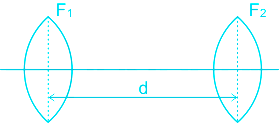
    • If two lens having focal length f1 and f2seprated by distance 'd' then their equivalent power

    ​P = P₁ + P2 – dP₁P

    \(\frac{1}{f} = \frac{1}{f_1} + \frac{1}{f_2} - \frac{d}{f_1f_2}\)

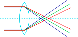
    Chromatic aberration (CA):

    • Chromatic aberration is a phenomenon in which light rays passing through a lens focus at different points, depending on their wavelength. 
    • The combination of two thin lenses in which their combination is free from chromatic aberration is called the achromatic combination of lenses ·

    Calculation:

    Consider two convex lenses of focal length f1 and f2 separated by distance d

    For a combination of lenses, we know that, equivalent focal length

    \(\frac{1}{f} = \frac{1}{f_1} + \frac{1}{f_2} - \frac{d}{f_1f_2}\)      ....(1)

    After differentiating the equation, we get

    \(⇒ -\frac{df}{f^2} = -\frac{df_1}{f_1^2} - \frac{df_2}{f_2^2} - d[\frac{-df_1}{f_1^2f_2} - \frac{df_2}{f_2^2f_1}]\)    ....(2)

    Let,  \(-\frac{df_1}{f_1} = ω _1\) and \(-\frac{df_2}{f_2} = ω _2\)

    Where ω is the dispersive power for lens medium 

    According to the question, lens have equal deflection ability,

    ⇒ ω1 = ω2 

    Hence, from equation (2)

     \(⇒ -\frac{df}{f^2} = \frac{\omega }{f_1} +\frac{\omega }{f_2} - \frac{d}{f_1f_2} (\omega + \omega )\)

    \(⇒ -\frac{df}{f^2} = \frac{\omega }{f_1} +\frac{\omega }{f_2} - \frac{d}{f_1f_2} (2\omega )\)    ....(3)

    Now, it is given that, deviation provided by the lens is the same. It means the focal length of all colours is the same. i.e. the combination is apparently free from chromatic aberration.

    Hence, for achromatic to be minimum, the focal length of combination for all colour must be the same. Therefore,

    df = 0

    \(\Rightarrow \frac{\omega }{f_1} +\frac{\omega }{f_2} - \frac{d}{f_1f_2} (2\omega ) = 0\)

    \(\Rightarrow d = \frac{f_1 + f_2}{2}\)

    Therefore, the distance b/w two lenses must be equal to their average individual length.

Self Studies
User
Question Analysis
  • Correct -

  • Wrong -

  • Skipped -

My Perfomance
  • Score

    -

    out of -
  • Rank

    -

    out of -
Re-Attempt Weekly Quiz Competition
Self Studies Get latest Exam Updates
& Study Material Alerts!
No, Thanks
Self Studies
Click on Allow to receive notifications
Allow Notification
Self Studies
Self Studies Self Studies
To enable notifications follow this 2 steps:
  • First Click on Secure Icon Self Studies
  • Second click on the toggle icon
Allow Notification
Get latest Exam Updates & FREE Study Material Alerts!
Self Studies ×
Open Now