-
Question 1
5 / -1
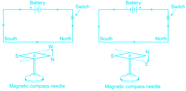
The magnetic effect of current was discovered by
Solution
CONCEPT:
- Oersted’s experiment: Hans Christian Oersted was a Danish scientist who explored the relationship between electric current and magnetism.
- The wire will carry a current that creates a magnetic field around itself. Bringing the compass near the wire or in the loop will cause the compass needle to move.
- The current had produced a magnetic field strong enough to cause the compass needle to turn.
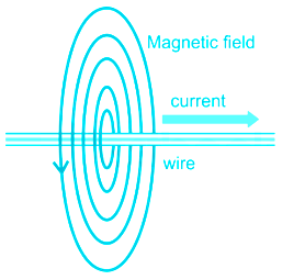
EXPLANATION:
- Oersted’s experiment explains that when an electric current passes through a conducting wire, a magnetic field is produced around the wire.
- Thus the magnetic effect of current was discovered by Oersted. So option 3 is correct.
-
Question 2
5 / -1
The wavelength of photon is 0.01Å. If h be the Plank's constant, its momentum will be -
Solution
Concept:
The relationship between wavelength and momentum of any particle is given by De Broglie Equation.
\(λ = \frac{h}{p}\) -- (1)
λ is the wavelength of the wave associated, h is Planck's constant, p is momentum.
Calculation:
Wavelength λ = 0.01Å. = 0.01 × 10 -10 m = 10 -12 m
So, λ = 10 -12 m -- (2)
From Eqution (1), we can say that,
\(p= \frac{h}{\lambda }\)
Putting (2) in this
\(\implies p= \frac{h}{10^{-12} }\)
⇒ p = 10 12 h
So, the correct option is 10 12 h
-
Question 3
5 / -1
The focal length of a convergent lens is R. Now if the lens is dipped into the water of refractive index 1.33, then the focal length of the lens will be (refractive index of the material of lens = 1.5):
Solution
CONCEPT:
Lens Maker's Formula:
- If R1 and R2 are the radii of curvature of first and second refracting surfaces of a thin lens of focal length f and refractive index μ (w.r.t. surrounding medium) then the relation between f, μ, R1 and R2 are known as lens maker’s formula.
\(\frac{1}{f} = \left( {μ - 1} \right)\left( {\frac{1}{{{R_1}}} - \frac{1}{{{R_2}}}} \right)\)
CALCULATION:
Give - Refractive index of a water (μw) =1.33 and focal length of a lens (f1) = R cm and refractive index of a lens (μl) = 1.5
- When light passes from air to lens, then its focal length is
\(⇒ \frac{1}{f_1} = \left( {μ_l - 1} \right)\left( {\frac{1}{{{R_1}}} - \frac{1}{{{R_2}}}} \right)\) --------------- (1)
- If the lens is dipped into the water of refractive index 1.33, then the focal length of the lens will be
\(⇒ \frac{1}{f} = \left( {\frac{μ_l}{\mu_w} - 1} \right)\left( {\frac{1}{{{R_1}}} - \frac{1}{{{R_2}}}} \right)\) ---------------- (2)
On dividing equation 1 by 2, we get
\( ⇒ \frac{{{f}}}{f_1} = \frac{{\left( {{\mu _l} - 1} \right)}}{{\left( {\frac{{{\mu _l}}}{{{\mu _w}}} - 1} \right)}}\)
\( ⇒ \frac{{{f}}}{{R}} = \frac{{\left( {1.5 - 1} \right)}}{{\left( {\frac{1.5}{{1.33}} - 1} \right)}} =4\)
⇒ f = 4R
-
Question 4
5 / -1
The refractive index for a glass is 1.62. The sine of the critical angle for total internal refection at a glass-air interface is:
Solution
Concept:
Refraction of Light: When a ray of light is traveling from one transparent medium to another, it bends its path. This phenomenon is called refraction.
When the light changes its medium, its speed, and wavelength changes.
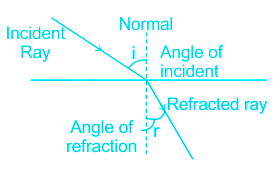
Where i is the angle of incidence, r is the angle of refraction.
Refractive Index:
The ratio of the speed of light in the vacuum to the speed of light in a given transparent medium is called the refractive index of the medium.
- When light travels from a medium with a higher refractive index to a lower one, then it bends away from normal. The angle of refraction is more than the angle of incidence.
- When light travels from a medium with a lower refractive index to a higher one, then it bends toward normal. The angle of refraction is less than the angle of incidence.
Snells Law of Refraction: The ratio of the sine of the angle of incidence to the sine of the angle of refraction is constant for two transparent medium.
\(\frac{sin\; i}{sin\; r} = \;\frac{n_2}{n_1}\)
n2 is the medium in which light is entering, n1 is the initial medium of light
When the ray of light is traveling from the medium with a higher refractive index to a lower one, for example, water to air, and the angle of refraction formed is 90 ° then the angle of incidence at that point is critical angle.
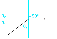
When medium 2 is air having refractive index n2 = 1, and medium 1 have refractive index n1 = μ, then critical angle θc can be represented by
\(\frac{sin\; θ_c}{sin \;90 °} = \frac{1}{μ}\)
\(\implies sin\; θ_c= \frac{1}{μ}\)
- The sine of critical angle is reciprocal of refractive index.
- When the incidence angle is more than the critical angle, then the ray of light reflects back in the same medium. This phenomenon is called Total Internal Reflection.
Calculation:
Given refractive index μ = 1. 62
\(sin\; θ_c= \frac{1}{μ}\)
\(sin\; θ _c= \frac{1}{1.62}\)
sin θc = 0. 62
So, 0.62 is the correct option.
-
Question 5
5 / -1
The magnetic moment (m) of a current loop = _________. ('I' is the current in the loop and 'A' is the area of the rectangular loop)
Solution
Concept:
- If the circular loop is considered as a magnetic dipole, then the dipole moment is the product of current and area. But the circular loop has multiple numbers of turns.
- Therefore, the magnitude of dipole moment = area × current × number of turns.
i.e. m = NIA = NI (π r2)
where, Magnetic moment of copper coil = m
No of loops = N
Current flowing though loop = I
Area of coil = r
Explanation:
From the above explanation we can see that, magnetic moment of circular coil with N number of terms is expressed as
m = NIA
Now for a sing loop the above equation can be expressed as
m = IA
-
Question 6
5 / -1
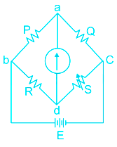
The Wheatstone’s bridge is said to be balanced, when:
(i) Vd = Va
(ii) Zero flow current through galvanometer.
Solution
CONCEPT:
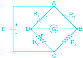
- Wheatstone bridge: It is an arrangement of four resistance connected to form the arms of a quadrilateral. A battery with key and galvanometer is connected along its two diagonals respectively.
- The Wheatstone bridge works on the principle of null deflection, i.e. the ratio of their resistances is equal, and no current flows through the galvanometer.
- Null Deflection: An instrument in which zero or null indication determines the magnitude of measured quantity such type of instrument is called a null deflection type instrument.
- To find the value of an unknown resistance:
\(\frac{{{{\bf{R}}_1}}}{{{{\bf{R}}_3}}} = \frac{{{{\bf{R}}_2}}}{{{{\bf{R}}_{\bf{x}}}}}\)
Where R1, R2, and R3 are the known resistor, and Rx is an unknown resistor.
EXPLANATION:
- Balanced bridge: The bridge is said to be balanced when deflection in the galvanometer is zero i.e. no current flows through the galvanometer or in other words VB = VD.
- In the balanced condition \(\frac{P}{Q} = \frac{R}{S}\), on mutually changing the position of cell and galvanometer, this condition will not change.
- Thus, both the given statements are correct.
-
Question 7
5 / -1
The frequency of incident photon is reduced in a photoelectric emission process then the stopping potential will-
Solution
CONCEPT:
- Photoelectric effect: When a light of sufficiently small wavelength is incident on the metal surface, electrons are ejected from the metal instantly. This phenomenon is called the photoelectric effect.
- Stopping potential: The photocurrent may be stopped by applying a negative potential to anode w.r.t. cathode. The minimum potential required to stop the electron emitted from metal so that its kinetic energy becomes zero.
- Work function: It is the minimum amount of energy required so that metal emits an electron. It is represented with ϕ. Its unit is eV or joules.
- It is having different values for different metals.
Einstein’s equation for photoelectric effect is given by:
h ν = ϕ + K.E
Where h = planks constant = 6.6 × 10-34 = 4.14 × 10⁻¹⁵ eV-s, ν = incident frequency, ϕ = work function
The relation between maximum kinetic energy and stopping potential is given by:
KEMax = e VS
Where e is charge on an electron and VS is stopping potential (e = 1.6 × 10⁻¹⁹ C)
EXPLANATION:
The Einstein’s equation becomes:
h ν = ϕ + e VS
So VS = (h/e) ν + ϕ/e
- Thus the stopping potential is linearly proportional to the incident frequency of the photon. So when we reduce the frequency of the incident photon then the stopping potential will reduce. So option 2 is correct.
-
Question 8
5 / -1
Find the potential energy of an electric dipole of dipole moment 12 C m which is placed in an electric field of magnitude 6 N/C. The angle between dipole and the electric field is 60°
Solution
Concept:
Electric dipole:
- When two equal and opposite charges are separated by a small distance then this combination of charges are called as electric dipole.
- The multiplication of charge and the distance between them is called as electric dipole moment.
- Electric dipole moment is denoted by P and the SI unit of dipole moment is Coulomb-meter (C⋅m)
Dipole moment = P = q × d
Where q is charge and d is distance between two charge particles.
- The direction electric dipole moment is from negative charge to positive charge.
- The space or region around the electric charge in which electrostatic force can be experienced by other charge particle is called as electric field by that electric charge.
Electric potential energy of an electric dipole moment placed in an electric field is given by:
Potential energy = E = PE Cosθ
Where θ is the angle between dipole and electric field and E is electric field.
Explanation:
Given that:
Dipole moment = P = 12 Cm
Electric field = E = 6N/C
Potential energy = PE Cosθ = 12 × 6 × Cos (60°)
\(PE = 12 \times 6 \times \frac{1}{2}= 36 J\)
-
Question 9
5 / -1
The coils of a step-down transformer have 500 turns and 5000 turns. In the primary coil, a current of 4 A at 2200 volts is sent. The value of the current in the secondary coil will be
Solution
CONCEPT:
Transformer:
- An electrical device that is used to transfer electrical energy from one electrical circuit to another is called a transformer.
There are two types of transformer:
1. Step-up transformer:
- The transformer which increases the potential is called a step-up transformer.
- The number of turns in the secondary coil is more than that in the primary coil.
2.Step-down transformer:
- The transformer which decreases the potential is called a step-down transformer.
- The number of turns in the secondary coil is less than that in the primary coil.
As in an ideal transformer, there is no loss of power i.e.
Pout = Pin
So, VsIs = VpIp
\(\therefore \frac{{{V_s}}}{{{V_p}}} = \frac{{{N_s}}}{{{N_P}}} = \frac{{{I_P}}}{{{I_S}}}\)
Where Ns = number of turns of the secondary coil, NP = number of turns of the primary coil, Vs = Voltage secondary coil, VP = Voltage primary coil, Is = Current in the secondary coil and IP = current in the primary coil.
EXPLANATION:
Given – Np = 5000, Ns = 500, Ip = 4 A and Vp = 2200 V
The relation between the current and number of turns is given by
\(\frac{{{N_s}}}{{{N_P}}} = \frac{{{I_P}}}{{{I_S}}}\)
\( \Rightarrow {I_s} = \frac{{{I_P}{N_P}}}{{{N_S}}} = \frac{{4\left( {5000} \right)}}{{500}} = 40\;A\)
-
Question 10
5 / -1
If the drift velocity of electrons is 6.7 × 10⁻⁵ ms-1, calculate the electron mobility when an electric field of 3.35 Vm-1 is applied across a conductor.
Solution
CONCEPT:
Mobility:
- the magnitude of drift velocity per unit electric field is called mobility.
- it is denoted by µ.
\(\Rightarrow \mu =\frac{\begin{vmatrix} v_{d} \end{vmatrix} }{E}\) where vd is the drift velocity, and E is the electric field.
- SI unit of mobility is m2/ Vs.
- Mobility is a positive quantity.
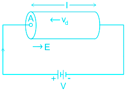
- Drift velocity: Under the influence of the external electric field, drift velocity is the average velocity with which electrons get drifted towards the positive end of the conductor. The drift velocity of electrons is of the order of 10-4 ms-1.
\(\Rightarrow \mu =\frac{\begin{vmatrix} v_{d} \end{vmatrix} }{E}=\frac{q\tau }{m}\) , where, \(v_{d}= \frac{qE\tau }{m}\) q is the charge, E is the electric field and \(\tau\)is the relaxation time.
- Relaxation time = mean free path of electron/ drift speed of electrons.
CALCULATION:
Given: drift velocity (vd ) = 6.7 × 10⁻⁵ ms-1 and electric field (E) = 3.35 Vm-1
- Mobility of the electron is,
\(\Rightarrow \mu =\frac{\begin{vmatrix} v_{d} \end{vmatrix} }{E} =\frac{6.7 \times 10^{-5}}{3.35}= 2 \times 10^{-5} m^{2}V^{-1}s^{-1}\). Hence correct
option is 1).
-
Question 11
5 / -1
What should be the properties of the core of electromagnets?
Solution
CONCEPT:
Electromagnet:
- An electromagnet is a type of magnet in which the magnetic field is produced by an electric current.
- Electromagnets usually consist of wire wounds into a coil.
- The magnetism of the electromagnets can be increased by placing a soft iron rod inside the solenoid.
- The core of electromagnets is made of ferromagnetic materials which have high permeability and low retentivity.
- Electromagnets are used in electric bells, loudspeakers, and telephone diaphragms.
- Giant electromagnets are used in cranes to lift machinery, and bulk quantities of iron and steel.
EXPLANATION:
- The magnetism of the electromagnets can be increased by placing a soft iron rod inside the solenoid.
- The core of electromagnets is made of ferromagnetic materials which have high permeability and low retentivity. Hence, option 1 is correct.
-
Question 12
5 / -1
Two plates are at potentials -10 V and +30 V. If the separation between the plates is 2 cm then find the electric field between them.
Solution
CONCEPT:
Electric potential (V):
- The potential difference between two points in an electric field may be defined as the amount of work done in moving a unit positive charge from one point to the other against the electrostatic force i.e.,
\({\rm{Electric\;potential\;}}\left( {\rm{V}} \right) = \frac{{{\rm{Work\;done\;}}\left( {\rm{W}} \right)}}{{{\rm{Charge\;}}\left( {\rm{q}} \right)}}\)
- Relationship between the electric field (E), an electric potential (V) ,and distance (r) is given by -
\(dE = - \frac{{dV}}{{dr}}\)
- The electric field is a derivative of potential difference.
- The negative sign shows that the direction of E is opposite to the direction of dv i.e., dv decreases along the direction of E.
CALCULATION:
Given - Distance between the plates (d) = 2 cm = 0.02 m
The relationship between the electric field (E), an electric potential (V), and distance (r) is given by
\(E = \frac{V}{d}\)
Potential difference (V) = 30 – (-10 V) = 40 V
∴ Electric field between the plates is
\(⇒ E= \frac{V}{d}\)
\(⇒ E= \frac{{40}}{{0.02}}\)
⇒ E = 2000 V/m
-
Question 13
5 / -1
Carbon resistors are made in —
Solution
Carbon resistors are made in both composition and film type.
Composition type carbon resistors are made by compressing carbon powder while using a suitable resin binder.
Film type carbon resistors are made by depositing hydrocarbon vapours on a ceramic capillary pipe at 900 to 1100° C temperature.
-
Question 14
5 / -1
The end product of the decay of 90Th232 is 82Pb208. The number of α and β-particles emitted are respectively
Solution
Concept:
Nuclear Decay: Nuclear decay is the process by which an unstable isotope of a particular element spontaneously transforms into a new element by the emission of ionizing radiation. Example: Decay of C-14 to C-12.
In the fission reaction α, β, and γ rays are released.
α-decay: when an α particle is leaving the parent atom
- It reduces the atomic number (Z) by 2.
- It reduces the atomic mass (A) by 4.
ZXA —→ Z-2XA-4 + 2α4
β-decay: when a β particle is leaving the parent atom
- It increases the atomic number (Z) by 1.
- It does not change in atomic mass.
ZXA —→ Z+1XA + -1β0
γ - Decay: it neither changes the atomic number nor atomic mass.
Calculation:
Given that:
90Th232 —→ 82Pb208 + x 2α4 + y -1β0
Applye the mass conservation:
232 = 208 + 4x + 0 × y
So x = 24/4 = 6 = Number of α particles
Applye the atomic number conservation:
90 = 82 + 2x - y = 82 + 12 - y
So y = 4 = Number of beta particles
Hence option 1 is correct.
-
Question 15
5 / -1
Wavelength of first line of Balmer series of Hydrogen is 6561 Å then the wavelength of second line of Balmer series will be :
Solution
The correct answer is option c) i.e. 4860 Ǻ.
CONCEPT:
- Rydberg's formula gives a relationship between the energy level difference in various levels of Bohr's model of an atom and the wavelength of absorbed or emitted photons during the excitation of electrons.
Rydberg formula: \(\frac{1}{λ} = RZ^2 [{ \frac{1}{n_i^2} - \frac{1}{n_f^2}}]\)
Where R is the Rydberg constant, Z is the atomic number, ni is the lower energy level and nf is the higher energy level.
Balmer series formula: \(\frac{1}{λ} = RZ^2 [{ \frac{1}{2^2} - \frac{1}{n_f^2}}]\)
Where nf > 2
CALCULATION:
Given that:
element is Hydrogen. Atomic number, Z = 1
The wavelength of the first line of Balmer series (nf = 3), λ1 = 6561 Å
Using the Balmer series formula,\(\frac{1}{λ_1} = R(1)^2 [{ \frac{1}{2^2} - \frac{1}{3^2}}]\)
\(\frac{1}{λ_1} = \frac{5R}{36}\) ----(1)
The wavelength of the second line of the Balmer series: \(\frac{1}{λ_2} = R(1)^2 [{ \frac{1}{2^2} - \frac{1}{4^2}}]\)
\(\frac{1}{λ_2} = \frac{3R}{16}\) ----(2)
Frome (1) and (2), \(\frac{λ_2}{λ_1} = \)\(\frac{\frac{16}{3R}}{ \frac{36}{5R}}\)\(= \frac{20}{27} \)
Therefore, λ2 = λ1 × \(\frac{20}{27} \) = 6561 × \(\frac{20}{27}\) = 4860 Ǻ
-
Question 16
5 / -1
Which of the following graphs correctly represents the variation of heat energy (U) produced in a metallic conductor in a given time as a function of potential difference (V) across the conductor?
Solution
CONCEPT:
- Heat Energy: Heat energy is generated in the conductor, when current flows through a conductor.
- The generated heat energy of an electric current depends on three factors:
- The resistance, R of the conductor. A higher resistance produces more heat.
- The time, t for which current flows. The longer the time the larger the amount of heat produced
- The amount of current, I. the higher the current the larger the amount of heat generated.
Heat Energy produced in a metallic conductor is given by
U = I2Rt
where H is heat generated, I is the current in the conductor, R is the resistance of the concductor, and t is the time in which heat is generated.
- Ohm's Law: A law stating that at a constant temperature electric current is proportional to voltage and inversely proportional to resistance.
V α I
V =IR or I = V/R
where V is the potential, I is the current and R is the resistance.
EXPLANATION:
- Heat Energy produced in a metallic conductor is given by
U = I2Rt
By Ohm's Law I=V/R
So U = V2t/R
U α V2
So the graph between U and V will be upward parabola (parobola X2 = 4aY)
So the correct answer is option 4.
-
Question 17
5 / -1
Two long current-carrying wires of equal length are placed parallel to each other and separated by a small distance, if the length of both the wires is doubled then the force per unit length on the wires will:
Solution
CONCEPT:
The force between two parallel currents:
- We know that there exists a magnetic field due to a conductor carrying a current.
- And an external magnetic field exerts a force on a current-carrying conductor.
- Therefore we can say that when two current-carrying conductors placed nearby each other will exert (magnetic) forces on each other.
- In the period 1820-25, Ampere studied the nature of this magnetic force and its dependence on the magnitude of the current, on the shape and size of the conductors, as well as, the distances between the conductors.
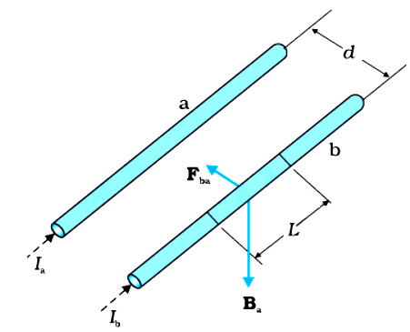
- Let two long parallel conductors a and b separated by a distance d and carrying (parallel) currents Ia and Ib respectively.
The magnitude of the magnetic field intensity due to wire a, on the wire b is,
\(\Rightarrow B_a=\frac{\mu_oI_a}{2\pi d}\)
The magnitude of the magnetic field intensity due to wire b, on the wire a is,
\(\Rightarrow B_b=\frac{\mu_oI_b}{2\pi d}\)
- The conductors 'a' and ‘b’ carrying a current Ia and Ib respectively will experience sideway forces due to magnetic field Bb and Ba respectively.
EXPLANATION:
- If two current-carrying long wires A and B are separated by a very small distance and placed parallel to each other. Then the force per unit length on wire A and wire b is given as,
\(\Rightarrow f_{AB}=f_{BA}=\frac{\mu_o I_AI_B}{2\pi d}\) -----(1)
Where IA = current in the wire A, IB = current in the wire B, and d = distance between the wires
- By equation 1 it is clear that the force per unit length on wire A and wire b does not depend on the lengths of wire A and wire B.
- So if the length of both the wires is doubled then the force per unit length on the wires will remain unchanged. Hence, option 3 is correct.
 Additional Information
The magnitude of the force on the segment L of the wire 'a' due to magnetic field Bb is given as,
\(\Rightarrow F_{ab}=\frac{\mu_o I_aI_b}{2\pi d}L\)
The magnitude of the force on the segment L of the wire 'b' due to magnetic field Ba is given as,
\(\Rightarrow F_{ba}=\frac{\mu_o I_aI_b}{2\pi d}L\)
The magnitude of the force per unit length on wire a and wire b is given as,
\(\Rightarrow f_{ab}=f_{ba}=\frac{\mu_o I_aI_b}{2\pi d}\)
 Important Points
- When the current flows in the same direction in the two parallel wires then both wires attract each other and if the current flows in the opposite direction in the two parallel wires then both wires repel each other.
-
Question 18
5 / -1
Two charges +q and -q are placed at points A(a,0) and B(-a,0) on the x-axis. The potential due to this system of charges on point P(r, θ) with position vector \(\vec r\)will be? Given that q, a are positive constants and r >> a.
Solution
CONCEPT :
- Electric potential is equal to the amount of work done per unit charge by an external force to move the charge q from infinity to a specific point in an electric field.
\(⇒ V=\frac{W}{q}\)
- Potential due to a single charged particle Q at a distance r from it is given by:
\(⇒ V=\frac{Q}{4\piϵ_{0}r}\)
Where,
ϵ0 is the permittivity of free space and has a value of 8.85 × 10⁻¹² F/m in SI units
- Potential due to a dipole with dipole moment \(\vec p\) at a point P(r,θ) having position vector \(\vec r\) with respect to the dipole moment orientation is given by (if r >> a):
\(⇒ V=\frac{⃗ p.⃗ r}{4\piϵ_{0}r^3}\)
EXPLANATION:
- Given:
- The dipole is placed at the origin

\(\Rightarrow \vec p = q \times 2a \hat i = 2qa \hat i\)
- The position vector of point P is \(\vec r\)
- Potential due to a dipole with dipole moment \(\vec p\) at a point P with position vector \(\vec r\) with respect to the dipole moment orientation is given by (if r >> a)
\(⇒ V=\frac{\vec p.\vec r}{4\piϵ_{0}r^3} = \frac{2a\hat i.\vec r}{4\piϵ_{0}r^3} = \frac{a\hat i.\vec r}{2\piϵ_{0}r^3}\)
Therefore option 2 is correct.
-
Question 19
5 / -1
The refractive index of core and cladding for a step index fibre is 1.52 and 1.41 respectively. Its critical angle at core cladding boundary is:
Solution
Concept:
- Optical fibers are transparent fibers and act as a light pipe to transmit light between its two ends. They are made up of silicon dioxide.
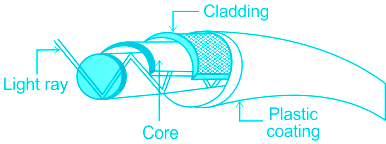
- Refractive index: The ratio of the speed of light in a vacuum to speed of light in a medium is called the refractive index of that medium.
- It is also called an absolute refractive index.
\(\mu = \frac{{Speed\;of\;light\;in\;vaccum\;\left( c \right)}}{{Speed\;of\;light\;in\;medium\;\left( v \right)}}\)
- Critical angle: When a ray of light is going from a denser medium to a rare medium then the angle of incidence at which the refraction angle is 90° is called as the critical angle.
The critical angle is given by:
ΘC = critical angle = Sin-1(n2/n1)
Where n2 is the refractive index of second medium in which light ray is going and n1 is the refractive index of first medium from which light is going to second medium.
Calculation:
Given: n1 = 1.52, n2 = 1.41
ΘC = critical angle = Sin-1(n2/n1)
\({\theta _c} = {\sin ^{ - 1}}\left( {\frac{{{n_2}}}{{{n_1}}}} \right)\)
\({\theta _c} = {\sin ^{ - 1}}\left( {\frac{{1.41}}{{1.52}}} \right)\)
Θc = 68.068°
-
Question 20
5 / -1
A 4μF capacitor is charged to 400 volts and then its plates are joined through a resistance of 1 kΩ. The heat produced in the resistance is:
Solution
Concept:
- The capacitance of a capacitor (C): The capacity of a capacitor to store the electric charge is called capacitance.
- The capacitance of a conductor is the ratio of charge (Q) to it by a rise in its potential (V).
- C = Q/V
- The unit of capacitance is the farad, (symbol F).
- Energy stored (U) in the capacitor is given by:
\(U = \frac{1}{2}C{V^2} = \frac{1}{2}\frac{{{Q^2}}}{C} = \frac{1}{2}\;QV\)
Where Q = charge stored on the capacitor, U = energy stored in the capacitor, C = capacitance of the capacitor and V = Electric potential difference
Calculation:
Given,
C = 4 μF = 4 × 10⁻⁶ F
Voltage applied = 400 V
Energy Stored = Heat energy produced through resistance.
\(U = \frac{1}{2}C{V^2} = \frac{1}{2} × {(4 × 10^{-6})} × {(400)}\)
⇒ Heat Produced = 32 × 10-2 Joule
⇒ Heat Produced = 0.32 Joule.
-
Question 21
5 / -1
How many α and β particles are emitted when \(Th_{90}^{232}\) changes to \(P_{82}^{208}\) ?
Solution
CONCEPT:
- Radioactive series are three naturally occurring radioactive decay chains and one artificial radioactive decay chain of unstable heavy atomic nuclei that decay through a sequence of alpha and beta decays until a stable nucleus is achieved.
- Most radioisotopes do not decay directly to a stable state and all isotopes within the series decay in the same way.
- An α-particle decay \(\left( {He_2^4} \right)\) reduces, mass number by 4, and atomic number by 2.
- A β - decay does not produce any change in mass number but it increases the atomic number by 1.
EXPLANATION:
\(\Rightarrow Th_{90}^{232} \to P_{82}^{208}\)
- A decrease in mass number = 232 – 208 = 24
- Number of α – particle emitted due to the above decrease in mass number = 24/4 = 6
- The expected decrease in atomic number due to emission of 6α – particle = 6 × 2 = 12
- The expected atomic number of the nucleus formed = 90 – 12 = 78
- But the atomic number of the nucleus formed = 82
- Increase in atomic number = 82 – 78 = 4
- Number of β – particles emitted = 4
- Thus 6α – particle and 4β – particle are emitted when \(Th_{90}^{232}\) changes to \(P_{82}^{208}\)
-
Question 22
5 / -1
A) 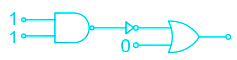
B) 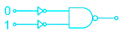
C) 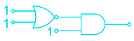
In the following combination of logic gates, the outputs of A, B and C are respectively
Solution
CONCEPT:
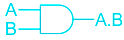
- AND Gate: The Logic AND Gate is a digital logic circuit whose output HIGH only when all the inputs are 1 (HIGH) otherwise output will be LOW.
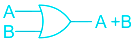
- OR Gate: The Logic OR Gate is a digital logic circuit whose output goes HIGH only when any one or more than one of its inputs is HIGH.
- NOT Gate: The Logic NOT Gate is the most basic of all the logic gates and is often referred to as an Inverting Buffer or simply an Inverter.
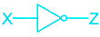
\(Y=\overline{A}\)
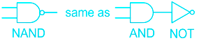
- NAND Gate: The logic Gate is obtained after adding NOT Gate after AND Gate.
\(Y=\overline{A.B}\)
- NOR Gate: The logic Gate is obtained after adding NOT Gate after OR Gate.
\(Y=\overline{A+B}\)

EXPLANATION:
For Circuit A:
- The output of NAND gate 0 and the output of NOT is 1.
- The output of the OR gate for input 1 and 0 is 1.
For Circuit B:
- The Output of NOT gate for 0 is 1 and of other NOT gate for input 1 is 0.
- The output of the NAND gate for input 1 and 0 is 1.
For Circuit C:
- The output for NOR Gate for input 1 and 1 is 0
- and the output of the AND gate for input 1 and 0 is 0.
- Hence the correct answer is option 2.
-
Question 23
5 / -1
What is the peak-to-peak voltage of a 2 VRMS sine wave ?
Solution
Concept:
For a sinusoidal alternating waveform
1. Peak to peak value of voltage (Vp-p) = 2 (Peak value) ---(1)
2. The peak value of voltage (Vp) = √2 Vrms ---(2)
3. RMS value of voltage \(\left( {{V_{rms}}} \right) = \dfrac{{{V_p}}}{{\surd 2}}\)
4. The average value of voltage \(\left( {{V_{avg}}} \right) = \dfrac{{2{V_p}}}{\pi }\)
Calculation:
Given:
Vrms = 2 V
From equation (2);
Vp = √2 × 2 V
From equation (1);
Vp-p = 2 × √2 × 2
∴ Vp-p = 5.656 V
-
Question 24
5 / -1
The resolving power of a telescope is R. If the wavelength of light used is tripled then the resolving power will become;
Solution
CONCEPT:
- The reciprocal of the smallest angle subtended at the objective lens of a telescope by two point objects which can be just distinguished as separate is called resolving power of a telescope.
The resolving power of a telescope is given by:
\(Resolving\;power\;\left( {R.P} \right) = \frac{D}{{1.22\;\lambda }}\)
Where D is distance between two point object and λ is wavelength of light used
EXPLANATION:
Given that: Initial resolving power (R.P) = R
Final wavelength (λ’) = 3 λ
\(New\;resolving\;power\;\left( {R.P} \right) = \frac{D}{{1.22\;\lambda '}} = \frac{D}{{1.22\; \times \;3\lambda }} = \frac{1}{3} \times R = \frac{R}{3}\)
-
Question 25
5 / -1
In a coil of area 20 cm2 and 10 turns with a magnetic field directed perpendicular to the plane and is changing at the rate of 107 gauss/sec. The resistance of the coil is 20 ohm. The current in the coil will be:
Solution
CONCEPT:
Faraday's first law of electromagnetic induction:
- Whenever a conductor is placed in a varying magnetic field, an electromotive force is induced.
- If the conductor circuit is closed, a current is induced which is called induced current.
Faraday's second law of electromagnetic induction:
- The induced emf in a coil is equal to the rate of change of flux linked with the coil.
\(⇒ e=-N\frac{dϕ}{dt}\)
Where N = number of turns, dϕ = change in magnetic flux and e = induced e.m.f.
- The negative sign says that it opposes the change in magnetic flux which is explained by Lenz law.
CALCULATION:
Given θ = 0, A = 20 cm2, N = 10, \(\frac{dB}{dt}\)= 107 gauss/sec, and R = 20 ohm
⇒ A = 20 cm2 = 20 × 10-4 m2
- The relation between the gauss and tesla is given by
⇒ 1 Gauss = 10-4 T
∴ \(⇒ \frac{dB}{dt}=10^7\, gauss/sec=10^3\,T/sec\)
- When the magnetic field is changing and the area remains constant, the magnetic flux is given as,
⇒ dϕ = A.dB.cosθ
⇒ dϕ = A.dB.cos0
⇒ dϕ = A.dB -----(1)
- By Faraday's law of electromagnetic induction, the magnitude of the induced emf in the coil is given as,
\(⇒ e=N\frac{dϕ}{dt}\)
\(⇒ e=NA\frac{dB}{dt}\)
⇒ e = 10 × 20 × 10-4 × 103
⇒ e = 20 V
By ohm's law, the current in the coil is given as,
\(⇒ I=\frac{e}{R}\) -----(2)
Where e = potential difference, and R = resistance
\(⇒ I=\frac{20}{20}\)
⇒ I = 1 A
- Hence, option 2 is correct.
-
Question 26
5 / -1
A single-phase transformer has 1000 turns on the primary and 400 turns on the secondary side. Find the transformer ratio of the transformer?
Solution
Concept:
Transformation ratio in a transformer is
\(K = \frac{{{N_2}}}{{{N_1}}} = \frac{{{V_2}}}{{{V_1}}} = \frac{{{I_1}}}{{{I_2}}}\)
N2 = secondary turns
N1 = Primary turns
V1 = Primary voltage
V2 = Secondary voltage
I1 = Primary current
I2 = Secondary current
Calculation:
Given
N2 = secondary turns = 400
N1 = Primary turns = 1000
\(K = \frac{{{N_2}}}{{{N_1}}} = \frac{{{400}}}{{{1000}}} \)
K = 0.4
Common mistake: Transformer ratio and transformation ratio both are different. The transformer ratio is the same as the turn's ratio.
-
Question 27
5 / -1
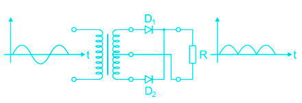
A full wave rectifier is operating from 50 Hz mains, the fundamental frequency in the ripple will be:
Solution
CONCEPT:
Rectifier:
- A rectifier is a device that converts an alternating current into a direct current. A p-n junction can be used as a rectifier because it permits current in one direction only.
- There are types of rectifier i.e. half-wave rectifier and full-wave rectifier.
- In a full-wave rectifier during a positive half cycle, one diode conducts and gives the output similarly in the negative half cycle another diode conducts and gives the output. Hence at a time, only one diode will be ON for one-half cycle.
- In the case of the full-wave rectifier, the fundamental frequency = 2 × main frequency.
CALCULATION:
Given - Main frequency = 50 Hz
- In the case of the full-wave rectifier,
⇒ Fundamental frequency = 2 × main frequency
⇒ Fundamental frequency = 2 × 50 = 100 Hz
-
Question 28
5 / -1
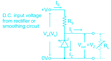
The __________ diode is designed to operate under reverse bias in the breakdown region and used as a voltage regulator.
Solution
CONCEPT:
- Zener diodes are normal PN junction diodes operating in a reverse-biased condition.
- Working of the Zener diode is similar to a PN junction diode in forwarding biased condition, but the uniqueness lies in the fact that it can also conduct when it is connected in reverse bias above its threshold/breakdown voltage.
- It is operated in a breakdown region.
- Peltier-diode: it uses the Peltier effect for giving or removing heat from the system by applying a voltage across it
- It is operated in a forward region
- A light-emitting diode (LED): The device which is used to produce the different intensity of light and different colour depending upon the types of mater used in making it is called LED.
- It is operated in a forward region
- Laser diode: It is just like a LED by produce highly energetic, polarized, monochromatic intense beam of light
- It is operated in a forward region
Explanation:
From the above explanation, we can see that Zener diode is the only one which can work in a breakdown region and can be used as voltage regulator as shown below.
Hence option 1 is correct among all
Extra points:
Zener diode is called Voltage regulator diode cause it maintains a constant voltage across its terminals called Zener voltage once the breakdown happens.
- Zener diode: A Semiconductor Diode blocks current in the reverse direction, but will suffer from premature breakdown or damage if the reverse voltage applied across becomes too high.
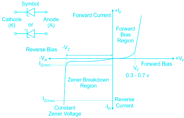
- Zener diode as voltage regulator: The Zener diode is connected with its cathode terminal connected to the positive rail of the DC supply so it is reverse biased and will be operating in its breakdown condition. Resistor Rs is selected so to limit the maximum current flowing in the circuit.
-
Question 29
5 / -1
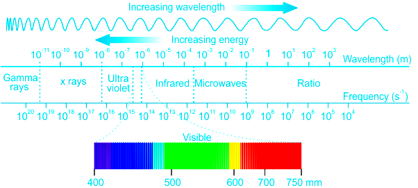
Which of the following electromagnetic waves have the maximum wavelength:
Solution
CONCEPT:
Electromagnetic waves or EM waves:
- The waves that are formed as a result of vibrations between an electric field and a magnetic field and they are perpendicular to each other and to the direction of the wave is called an electromagnetic wave.
- The accelerating charged particle produces an electromagnetic (EM) wave.
- A charged particle oscillating about an equilibrium position is an accelerating charged particle.
- Electromagnetic waves do not require any matter to propagate from one place to another as it consists of photons. They can move in a vacuum.
EXPLANATION:
The wavelength of different electromagnetic waves:
| Type of Radiation | Frequency Range (Hz) | Wavelength Range |
| gamma-rays | 1020 – 1024 | < 10-12 m |
| x-rays | 1017 – 1020 | 1 nm – 1 pm |
| ultraviolet | 1015 – 1017 | 400 nm – 1 nm |
| microwaves | 3 x 10¹¹ – 1013 | 1 mm – 25 μm |
- From the above table, it is clear that the wavelength of microwaves is maximum among the gamma rays, x-rays, and ultraviolet rays. Hence, option 3 is correct.
-
Question 30
5 / -1
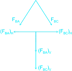
In an isosceles triangle, the side AB and BC are equal. If the charge at A and C are fixed and the charge at B can move, then how the charges +q, +q, and -q will be placed on the vertex, such that the charge at B will move perpendicular to the side AC?
Solution
CONCEPT:
The force between multiple charges:
- Experimentally, it is verified that force on any charge due to a number of other charges is the vector sum of all the forces on that charge due to the other charges, taken one at a time.
- The individual forces are unaffected due to the presence of other charges. This is termed as the principle of superposition.
- The principle of superposition says that in a system of charges q1, q2, q3,..., qn, the force on q1 due to q2 is the same as given by Coulomb’s law, i.e., it is unaffected by the presence of the other charges q2, q3,..., qn. The total force F1 on the charge q1, due to all other charges, is then given by the vector sum of the forces F12, F13, ..., F1n.
\(⇒ \vec{F_1}=\vec{F_{12}}+\vec{F_{13}}+...+\vec{F_{1n}}\)
EXPLANATION:
Case 1: When we place the charges like,
At A: +q, at B: +q and at C: -q
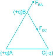
- The magnitude of all the charges is equal.
- The distance between point A and Point B is equal to the distance between point B and point C.
- So the force FBA will be equal to FBC.
⇒ FBA = FBC
The components of the force FBA and FBC are given in the below figure.
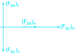
The vertical components and the horizontal components will be equal in magnitude.
⇒ (FBA)V = (FBC)V
⇒ (FBA)H = (FBC)H
- Since the vertical components are equal and opposite to each other so they will cancel each other.
- The horizontal components are equal and in the same direction so they will add to each other and the resultant force will be in the direction of these forces.
- So the resultant force on the charge at B will be in the horizontal direction towards point C, so in this case, the charge at B will move horizontally towards point C.
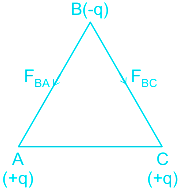
- Similarly, if we solve the situation for case 3 the charge at Point B will move horizontally towards point A.
The figure for case 3:
At A: -q, at B: +q and at C: +q
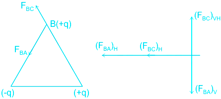
Case 2: When we place the charges like,
At A: +q, at B: -q and at C: +q
- The magnitude of all the charges is equal.
- The distance between point A and Point B is equal to the distance between point B and point C.
- So the force FBA will be equal to FBC.
⇒ FBA = FBC
The components of the force FBA and FBC are given in the below figure.
The vertical components and the horizontal components will be equal in magnitude.
⇒ (FBA)V = (FBC)V
⇒ (FBA)H = (FBC)H
- Since the horizontal components are equal and opposite to each other so they will cancel each other.
- The vertical components are equal and in the vertically downward direction so they will add to each other and the resultant force will be in the vertically downward direction.
- So the resultant force on the charge at B will be in the vertically downward direction perpendicular to the side AC, so in this case, the charge at B will move perpendicular to the side AC.
- Hence, option 2 is correct.
-
Question 31
5 / -1
In the Young’s double slit experiment, the width ratio of slit is 1 : 4 . Find the ratio of amplitude of light waves coming from them.
Solution
CONCEPT:
- When two waves of the same frequency, same wavelength, same velocity (nearly equal amplitude) moves in the same direction. Then their superimposition results in the interference.
- Due to interference, the resultant intensity of wave at that point is different from the sum of intensities due to each wave separately.
- Interference is of two types
- Constructive interference
- Destructive interference
- If w1 and w2 are the widths of the two slits from which intensities of light I1 and I2 emanates, then
\(\frac{{{w_1}}}{{{w_2}}} = \frac{{{I_1}}}{{{I_2}}} = \frac{{{a^2}}}{{{b^2}}}\)
Where a and b are the widths of the slits.
EXPLANATION:
Given - \(\frac{{{w}_{1}}}{{{w}_{2}}}=\frac{1}{4}\)
- From the above equation, it is clear that the width of the slit and intensity is given by -
\( \Rightarrow \frac{{{w_1}}}{{{w_2}}} = \frac{{{a^2}}}{{{b^2}}}\)
\( \Rightarrow \frac{1}{4} = \frac{{{a^2}}}{{{b^2}}}\)
Square root both side of the equation, we get
\(\Rightarrow \frac {a}{b}=\frac{1}{2}\)
- If the width ratio of the slit is 1 : 4, then the ratio of their amplitudes is 1 : 2. Therefore option 3 is correct
-
Question 32
5 / -1
If we increase the distance between the plates of a parallel plate capacitor by two times, what will be the change in potential difference between the plates?
Solution
CONCEPT:
- A parallel plate capacitor consists of two large plane parallel conducting plates of area A and separated by a small distance d.
- Mathematical expression for the capacitance of the parallel plate capacitor is given by
\(C=\frac{{{\epsilon }_{o}}A}{d}\)
Where C = capacitance, A = area of the two plates, εo = permittivity of free space and d = separation between the plates
EXPLANATION:
The electric field due to the parallel plate capacitor is given by
\(E = \frac{σ }{{{\varepsilon _o}}}\)
Where σ = surface charge density
- Relationship between the electric field (E), an electric potential (V) and distance (r) is given by
\(E = \frac{V}{d}\)
⇒ V = Ed
Where d = distance between the parallel plates of the capacitor.
- As we can see that the potential difference is proportional to the distance between the plates of the capacitors.
- Thus, the potential difference between the plates of the capacitors will become 2 times of the initial, when the distance between the plates get doubled. Therefore option 2 is correct.
-
Question 33
5 / -1
In order to investigate the internal atomic structure of crystals, we make use of:
Solution
X-rays:
- X-rays ionize gases through which they pass. Hence use to study atomic structure.
- Soft X-rays have a greater wavelength and lower frequency and hard X-rays have a lower wavelength and higher frequency.
- X-rays are not deflected by electric and magnetic fields.
- X-rays show all the important properties of light rays like reflection, refraction, interference, diffraction, and polarisation, etc.
- X-rays were discovered by scientist Roentgen.
Additional Information
1). Ultraviolet (UV) is a form of electromagnetic radiation with wavelengths from 10 (with a corresponding frequency around 30 PHz) to 400 nm (750 THz), shorter than that of visible light, but longer than X-rays.
2). Infrared radiation (IR), is a type of radiant energy that is invisible to human eyes but that we can feel as heat. All objects in the universe emit some level of IR radiation, but two of the most obvious sources are the sun and fire.
The heat that we feel from sunlight, a fire, a radiator or a warm sidewalk is infrared.
-
Question 34
5 / -1
If the radius of the circular current-carrying coil is increased, then what will be the impact on magnetic induction/magnetic field at the centre of a circular coil
Solution
Concept:
Biot Savart Law states that: The magnetic intensity (dB) at a point A due to current I flowing through a small element dl is Directly proportional to the current (I).
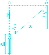
The magnetic field at the centre of the circular coil is given by
\(B = \frac{{{\mu _o}}}{{2\pi }}\frac{I}{r}\)
Where B = strength of the magnetic field, I = current, r = radius or distance
Explanation:
The magnetic field at the centre of the circular coil is given by;
\(B = \frac{{{\mu _o}}}{{2\pi }}\frac{I}{r}\)
So, the magnetic field is inversely proportional to the radius of the coil
\(B \propto \frac{1}{r}\)
So, if the
radius of the circular current-carrying coil is
increased, then the
magnetic field at the centre of the circular coil will
decrease.
-
Question 35
5 / -1
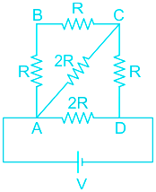
Find the equivalent resistance:
Solution
CONCEPT:
Resistance:
- The measurement of the opposition of the flow of electric current through a conductor is called resistance of that conductor. It is denoted by R.
There are mainly two ways of the combination of resistances:
1. Resistances in series:
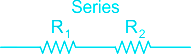
- When two or more resistances are connected one after another such that the same current flows through them are called resistances in series.
- The net resistance/equivalent resistance (R) of resistances in series is given by:
- Equivalent resistance, R = R1 + R2
2. Resistances in parallel:
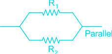
- When the terminals of two or more resistances are connected at the same two points and the potential difference across them is equal is called resistances in parallel.
- The net resistance/equivalent resistance(R) of resistances in parallel is given by:
\(⇒\frac{1}{R} = \frac{1}{{{R_1}}} + \frac{1}{{{R_2}}}\)
CALCULATION:
The given figure is,
- From the above figure, it is clear that the two resistance between point A and point C are in series. So the equivalent resistance of these two can be given as,
⇒ R1 = R + R
⇒ R1 = 2R -----(1)
The above figure can be further drawn as,
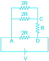
- In the above figure, the resistance between point A and point C are parallel so the equivalent resistance between A and C is given as,
\(⇒\frac{1}{R_{2}} = \frac{1}{{{2R}}} + \frac{1}{{{2R}}}\)
⇒ R2 = R -----(2)
The above figure can be further drawn as,
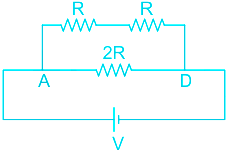
- The two resistance in the above branch are in series so the equivalent resistance for the above branch is given as,
⇒ R3 = R + R
⇒ R3 = 2R -----(3)
The above figure can be further drawn as,
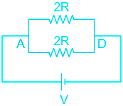
- In the above figure, the resistance are parallel so the equivalent resistance of the above figure is given as,
\(⇒\frac{1}{R_{eq}} = \frac{1}{{{2R}}} + \frac{1}{{{2R}}}\)
⇒ Req = RΩ
- Hence, option 2 is correct.
-
Question 36
5 / -1
The angle of dip at a certain location is 45∘. Then the relationship between horizontal component of Earth's magnetic field H and total intensity of Earth's magnetic field I is-
Solution
The correct answer is option 3) i.e. I = √2H
CONCEPT:
- The angle of dip (ϕ) is defined as the angle made by the earth’s magnetic field lines with respect to the horizontal.
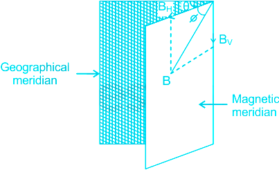
If B represents the direction of Earth's magnetic field, the angle of dip is given by
\(\Rightarrow tan \:ϕ = \frac{B_V}{B_H}\)
Where BV and BH are the vertical and horizontal components of Earth's magnetic fields.
EXPLANATION:
Given that:
The angle of dip, ϕ = 45∘
If I is the total intensity of the magnetic field of Earth at the location,
Horizontal component, \(H = Icos\phi = Icos45 =\frac{I}{\sqrt2} \)
\(\Rightarrow I = \sqrt2 H\)
-
Question 37
5 / -1
10 cells are connected in parallel with the internal resistance of 1 Ω and 1.5 Volts. the total voltage and total resistance is ______
Solution
Parallel grouping: In parallel grouping, all anodes are connected at one point and all cathode are connected together at other points.
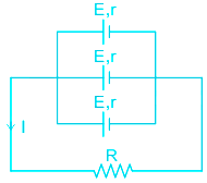
\(Equivalent\;EMF\left( E \right) = \;\frac{{\frac{{{E_1}}}{{{r_1}}} + \frac{{{E_2}}}{{{r_2}}} + \frac{{{E_3}}}{{{r_3}}}}}{{\frac{1}{{{r_1}}} + \frac{1}{{{r_2}}} + \frac{1}{{{r_3}}}}}\)
\(Equivalent\;internal\;resistance\;\left( r \right) = \frac{1}{{\frac{1}{{{r_1}}} + \frac{1}{{{r_2}}} + \frac{1}{{{r_3}}}}}\)
If n identical cells are connected in parallel
Equivalent emf of the combination Eeq = E
Equivalent internal resistance req = r/n
Calculation:
n = 10
E = 1.5 Volts
r = 1 Ω
∴ Equivalent emf of the combination = E = 1.5 Volts
Equivalent resistance of the combination = 1/n = 1/10 = 0.1 Ω

Series grouping: In series grouping anode of one cell is connected to the cathode of other cells and so on.
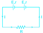
If n identical cells are connected in series
Equivalent emf of the combination Eeq = nE
Equivalent internal resistance req = nr
-
Question 38
5 / -1
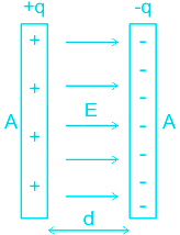
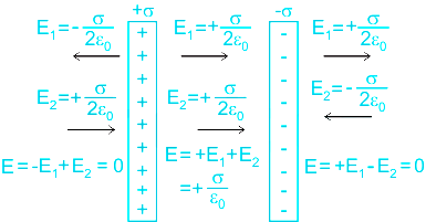
Two infinite plane parallel sheets having surface charge density +σ and –σ are kept parallel to each other at a small separation distance d. The electric field at any point in the region between the plates is
Solution
CONCEPT:
Gauss’s Law:
The total electric flux through a closed surface is 1/εo times the charge enclosed in the surface i.e. \({\rm{\Phi }} = \frac{q}{{{\epsilon_o}}}\)
But we know that Electrical flux through a closed surface is \(\oint \vec E \cdot \overrightarrow {ds} \)
\(\therefore\oint \vec E \cdot \overrightarrow {ds} = \frac{q}{{{\epsilon_o}}}\)
Where, E = electric field, q = charge enclosed in the surface, and εo = permittivity of free space.
Derivation:
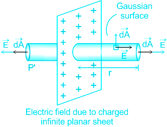
The electric field at a point due to an infinite sheet of charge is
\(E = \frac{\sigma }{{2{\epsilon_0}}}\)
Where
σ = surface charge density.
Here,
E1: Electric Field due to sheet having surface charge density +σ
E2: Electric Field due to sheet having surface charge density -σ
The electric field at any point in the region between the plates is
E = E1 + E2
\(E = \frac{\sigma }{{2{\epsilon_0}}} - \left( {\frac{{ - \sigma }}{{2{\epsilon_0}}}} \right) = \frac{{\sigma + \sigma }}{{2{\epsilon_0}}} = \frac{{2\sigma }}{{2{\epsilon_0}}} = \frac{\sigma }{{{\epsilon_0}}}\)
-
Question 39
5 / -1
The number of free electrons 'n' in an intrinsic semiconductor is proportional to
Solution
The correct answer is option 2) i.e. (temperature)3/2
CONCEPT:
- Intrinsic semiconductor: An intrinsic semiconductor is a pure semiconductor without any dopant species present in it.
- Since there are no impurities present in it, the number of free electrons equals the number of holes in an intrinsic semiconductor.
- Thus, the number of these charge carriers depends on the properties of the semiconductor material alone.
The carrier concentration (n) in an intrinsic semiconductor is given by:
\(n = BT^{3/2}e^{(\frac{-E_g}{2kT})}\)
Where B is the coefficient related to the type of semiconducting material used, Eg is the energy band gap in eV, k is the Boltzmann constant, and T is the temperature in Kelvin.
EXPLANATION:
- In an intrinsic semiconductor, the number of free electrons equals the number of holes.
- Therefore, the carrier concentration, n = number of free electrons
\(n = BT^{3/2}e^{(\frac{-E_g}{2kT})}\)
⇒ n ∝ T3/2
- Hence, the number of free electrons 'n' in an intrinsic semiconductor is proportional to (temperature)3/2
-
Question 40
5 / -1
If an alternating current is represented by i = 10 sin 314 t, where t is in seconds, then its frequency is around:
Solution
Concept:
Alternating Current (AC): A.C. means alternating current. It is a current that flow in the positive and negative direction periodically.
General equation of AC is
I = Io Sin ω t or,
I= Io Sin 2π f t
Where, Io = peak current., f = frequency, t = time, ω = angular velocity, I current.
Calculation:
Given: eqn of AC = i = 10 sin 314 t
Compare it with the general equation of current
I = Io Sin ω t
Io = 10 A, ω = 314.
ω = 2π f
so,
2π f = 314
2 × 3.14 f = 314
f = 100 / 2 = 50 Hz.
f = 50 Hz
-
Question 41
5 / -1
If the refractive index of water for red light is √3. Then find the Brewster angle for the air-water surface for a red light.
Solution
CONCEPT:
Brewster angle:
- The angle of incidence at which a beam of unpolarised light falling on a transparent surface is reflected as a beam of completely plane polarised light is called polarising or Brewster angle. It is denoted by ip.
- The relationship between the Brewster angle (ip) and refractive index (μ) is
μ = tan ip
- This relation is known as Brewster law.
CALCULATION:
Given - refraction index (μ) = √3
he relationship between the Brewster angle (ip) and refractive index (μ) is
μ = tan ip
⇒ ip = tan-1(μ) = tan-1(√3) = 60°
-
Question 42
5 / -1
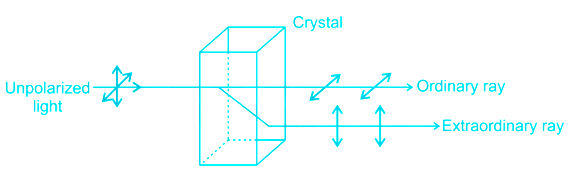
Which of the following optical phenomena CANNOT convert unpolarized light to light to plane polarized light?
Solution
Explanation:
Diffraction of light cannot convert unpolarized light into polarized light.
Polarization is defined as a phenomenon caused due to the wave nature of electromagnetic radiation.
- Sunlight travels through the vacuum to reach the Earth, which is an example of an electromagnetic wave.
- These waves are called electromagnetic waves because they form when an electric field that interacts with a magnetic field.
- There are two types of waves that are transverse waves, and longitudinal waves.
Diffraction of light is the phenomenon of bending of light from the sharp corners of a slit or obstacle and spreading into the region of geometrical shadow.
- Diffraction can occur only when the wavelength of light is comparable to the size of the obstacle or width of the slit.
- Diffraction is of two types:
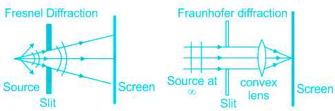
- Fresnel Diffraction - It is the type of diffraction which occurs when the light source lies at a finite distance from the slit.
- Fraunhofer Diffraction - It is the type of diffraction which occurs when a plane wavefront is incident on the slit and the wavefront emerging from the slit is also plane.
Additional Information
Scattering of light:
The incident in which light rays get deviated from its path when it strikes an obstacle like dust, water vapours, or gas molecules, etc.
Rayleigh's law of scattering: According to Rayleigh's law of scattering, the intensity of light of wavelength λ present in the scattered light is inversely proportional to the fourth power of λ, provided the size of the scattering particles is much smaller than λ. Mathematically,
\(I \propto \frac{1}{\lambda }\)
Thus the scattered intensity is maximum for shorter wavelength.
Scattering of InfraRed light is less than visible light.
Reflection:
The phenomena in which light ray is sent back into the same medium from which it is coming, on interaction with boundary, is called reflection
Laws of reflection:
The angle of incidence (θ i ) = Angle o f reflection (θ r )
The incident ray, the reflected ray, and normal to the surface of incidence always lies in the same plane.
Double refraction is an optical property in which a single ray of unpolarized light entering an anisotropic medium is split into two rays, each traveling in a different direction.
-
Question 43
5 / -1
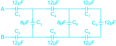
The total equivalent capacitance of the series parallel combination of capacitors across A and B shown in figure is
Solution
Concept:
Equivalent capacitance of capacitors -Connected in series: When n capacitors C1, C2, C3, ... Cn are connected in series, the net capacitance (Cs) is given by:
\(⇒ \frac{1}{C_s} = \frac{1}{C_1} + \frac{1}{C_2}+ \frac{1}{C_3} + ... \frac{1}{C_n}\)
Connected in parallel: When n capacitors C1, C2, C3, ... Cn are connected in parallel, the net capacitance (Cp) is given by:
⇒ Cp = C1 + C2 + C3 +... Cn
Calculation:
C7, C9 and C8 are in series,
12 μF, 12 μF, 12 μF
Equivalent capacitance = (1/12) + (1/12) + (1/12) = 4 μF
4 μF is in parallel with 8 μF
Equivalent capacitance = (4 + 8) μF = 12 μF
C4, C5 are in parallel with 12 μF
Equivalent = 4 μF
C3 is in series with 8 μF
Total equivalent = 12 μF
C1 and C2 are parallel to 12 μF
Hence equivalent = 4 μF
-
Question 44
5 / -1
If 2 kg of a substance is fully converted into energy, how much energy energy is produced
Solution
Correct option-3
Concept:
- According to Einstein's theory of relativity, mass is a condensed(occupied in a small volume) form of energy which simply means that mass can be converted into energy and vice-versa.
- The mass-energy equivalence concluded that whenever we have mass, it means we got lots of energy just sitting inside the mass.
- The mass-energy equivalence is given by Einstein's famous relation as:-
E = mc2..(i)
Where,
- E = Energy produced
- m = mass of matter in kg to be converted into energy
- c = \(3\times {{10}^{8}}\text{ m/s}\) (speed of light in free space or vacuum)
Calculation:
Given-
m = 2kg and c = \(3\times {{10}^{8}}\text{ m/s}\)
On substituting the given values in the above equation (i), we get
\(E=2\times {{\left( 3\times {{10}^{8}} \right)}^{2}}J\)
\(\Rightarrow E=2\times 9\times {{10}^{16}}J\)
\(\therefore E=18\times {{10}^{16}}J\)
Therefore the required energy produced is \(18\times {{10}^{16}}J\)

- Einstein's mass-energy equivalence is widely used to understand nuclear fission and fusion reaction. By using the famous equation E = mc2. It has revealed that a large amount of energy is liberated during nuclear fission and fusion reaction.
- The radioactive phenomenon of the various elements is based on mass-energy equivalence.
- Einstein's equation is used to find the change in mass of the nuclear reactions and can be used to find the binding energy of an atom.
-
Question 45
5 / -1
An astronomical telescope is focused on a distant star. If the distance between the objective lens and the eye piece is 2.5 m and the power of eye piece is 4D:
Solution
Concept:
Telescope:
- The instrument which makes the distant object appear nearer is called a telescope.
- The telescope has two convex lenses- one of them is called as an objective lens and another one is known as the eyepiece
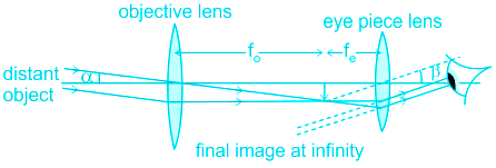
The magnification of a telescope is given by:
M = f0/fe
D = f0 + fe
Where f0 is the focal length of the objective and fe is the focal length of the eyepiece.
Calculation:
Given,
The distance between the objective lens and the eyepiece is (D) = 2.5 m
We know that, power of the lens = 1/f
Here, Power of eyepiece = 4 Dioptre
\(\Rightarrow Power = 4 = \frac{1}{{{f_e}}} \Rightarrow {f_e} = \frac{1}{4} = 0.25\;m\)
Also, D = f0 + fe
⇒ 2.5 m = f0 + 0.25 m
⇒ f0 = 2.5 m – 0.25 m = 2.25 m
\(Power\;of\;objective\;lens\;\left( P \right) = \frac{1}{{{f_0}}} = \frac{1}{{2.25}} = 0.44\;D\)
Hence, the power of objective lens = 0.44 Dioptre.
-
Question 46
5 / -1
What will be the magnetic dipole moment at the center, if a straight copper wire is bent into a circular loops of 50 turns with constant current 6 A and radius of 2 cm
Solution
Concept:
If the circular loop is considered as a magnetic dipole, then the dipole moment is the product of current and area. But the circular loop has multiple numbers of turns.
Therefore, the magnitude of dipole moment = area × current × number of turns.
i.e. M = NIA
where, Magnetic moment of copper coil = M
No of loops = N
Current flowing though loop = I
Area of coil = r
Calculation:
Given:
Current flowing in a loop = 6 A
Radius of loop = 2 cm = 0.02 m
Number of turns = 50
Therefore magnetic moment for a copper coil can be given as,
(M) = N× I× (πr2)
M = 50 × 6 ×π × (0.02)2
∴ M = 0.37 Am2
-
Question 47
5 / -1
If 5.0 μC charge is placed at the center of a Gaussian surface in the form of a cube. The electric flux through any one face of the cube is:
Solution
Gauss’s Law:
The total of the electric flux out of a closed surface is equal to the charge (Q) enclosed divided by the permittivity (ϵ0) of the medium. It can be given by ϕE
\({ϕ _{\bf{E}}} = \frac{{\bf{Q}}}{{{\epsilon_0}}}\)
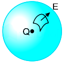
Analysis:
A charge is placed at the center of the cube as shown:
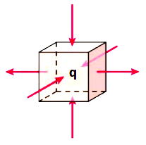
Flux is linked equally with all the faces (6 faces)
∴ Using Gauss’s theorem, the flux linked with 1 face will be:
\({{ϕ }_{E}}=\frac{q}{{{\epsilon }_{0}}}\)
As a cube is given, flux linked with 6 faces are:
\(6× {{ϕ }_{E}}=\frac{q}{{{\epsilon }_{0}}}\)
\({{ϕ }_{E}}=\frac{q}{6~{{\epsilon }_{0}}}\)
Calculation:
With q = 5.0 μC, the electric flux through any one face of the cube will be:
\({{ϕ }_{E}}=\frac{5× 10^{-6}}{6~{× 8.854× 10^{-12}}}\)
ϕE = 9.4 × 10⁴ N m2/C
-
Question 48
5 / -1
A current of 1.0 A is drawn by a filament of an electric bulb for 10 minutes. The amount of electric charge that flows through the circuit is
Solution
CONCEPT:
Electric current:
- The flow of electric charges through a conductor constitutes an electric current.
- Quantitatively, electric current in a conductor across an area held perpendicular to the direction of flow of charge is defined as the amount of charge flowing across that area per unit time i.e.,
\({\rm{Electric\;curernt\;}}\left( {\rm{I}} \right) = \frac{{{\rm{Electric\;charge}}\;\left( {\rm{Q}} \right)}}{{{\rm{Time\;}}\left( {\rm{t}} \right)}}\)
- SI unit of current is ampere and it is denoted by the letter A.
CALCULATION:
Given - Electric current (I) = 1 A and time (t) = 10 minutes = 600 sec
- The amount of electric charge that flows through the circuit is\
⇒ Q = I × t
⇒ Q = 1 × 600 = 600 C
-
Question 49
5 / -1
Two coherent light beams of wavelength λ are superimposed at a point. If the resultant intensity at that point is zero, then the possible path difference between the two waves at that point is:
Solution
CONCEPT:
Coherent addition of waves:
- The phenomenon in which two or more waves superpose to form a resultant wave of greater, lower, or the same amplitude is called interference.
- The interference is based on the superposition principle according to which at a particular point in the medium, the resultant displacement produced by a number of waves is the vector sum of the displacements produced by each of the waves.
- Let two sources of wave S1 and S2 are coherent.
- Let the intensity of the waves are Io.
For constructive interference:
- If at any point the waves emerging from the coherent sources S1 and S2 are in phase then we will have constructive interference and the resultant intensity will be 4Io.
⇒ Path difference = nλ and n = 0,1,2,3,...
For destructive interference:
- If at any point the waves emerging from the coherent sources S1 and S2 are in opposite phase then we will have destructive interference and the resultant intensity will be zero.
⇒ Path difference = \(\left ( n+\frac{1}{2} \right )\)λ and n = 0,1,2,3,...
Where λ = wavelength
CALCULATION:
For destructive interference:
- If at any point the waves emerging from the coherent sources S1 and S2 are in opposite phase then we will have destructive interference and the resultant intensity will be zero.
⇒ Path difference = \(\left ( n+\frac{1}{2} \right )\)λ and n = 0,1,2,3,...
Where λ = wavelength
- In the given case the resultant intensity is zero, so there will be destructive interference.
- For destructive interference, the possible path differences between the waves are given as,
For n = 0,
⇒ Path difference = 0.5λ
For n = 1,
⇒ Path difference = 1.5λ
For n = 2,
⇒ Path difference = 2.5λ
- So it is clear that when the path difference is λ and \(\frac{λ}{3}\), there will be no destructive interference.
- The destructive interference will occur when the path difference between the waves is 2.5λ.
- Hence, option 3 is correct.
-
Question 50
5 / -1
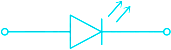
The following figure represents
Solution
A light-emitting diode (LED):
The device which is used to produce the different intensity of light and different colors depending upon the types of mater used in making it is called LED.
The symbolic representation of the LED is as shown:
Additional Information
PN Junction Diode:
- A unilateral device is a device that conducts only in one direction.
- p-n junction diodes conduct only when the p region is connected to a higher voltage and the n region is connected to lower voltage.
- When reverse biased, it acts as an open circuit.
- The symbol for a diode is as shown:

Zener diodes
- Zener diodes are normal PN junction diodes operating in reverse-biased conditions.
- The working of the Zener diode is similar to a PN junction diode in the forward biased condition, but the uniqueness lies in the fact that it can also conduct when it is connected in reverse bias above its threshold/breakdown voltage.
- Zener diodes also called avalanche diodes or Breakdown diodes are the heavily doped P – N junction diodes
- It is operated in a breakdown region.
The symbolic representation of the Zener diode is as shown:

Photo-diode:
1) It is a light-sensing device that is used to sense the intensity of light
2) Some of the examples are the smoke detector, a receiver in tv for converting remote signals, etc.
The symbolic representation of the Photodiode is as shown:


 ×
×

 Sign in
 Profile
 Signout


