Self Studies

Physics Test - 33

Result Self Studies

Physics Test - 33
  • Score

    -

    out of -
  • Rank

    -

    out of -
TIME Taken - -
Self Studies
Weekly Quiz Competition
  • Question 1
    1 / -0

    A train moves towards a stationary observer with speed 34 m.s−1. The train sounds a whistle and its frequency registered by the observer is f1. If the train's speed is reduced to 17 m.s−1, the frequency registered is f2. If the speed of sound is 340 m.s−1, then the ratio f1 / f2

    Solution
    \begin{array}{l}
    \text { Here, } v_{s_{1}}=34 \mathrm{ms}^{-1} \\
    v=340 \mathrm{ms}^{-1} \\
    f_{1}=\frac{v \times n}{v-v_{s_{1}}}=\frac{340 \times n}{340-34}=\frac{340}{306} n \\
    f_{2}=\frac{v \times n}{v-v_{s_{2}}}=\frac{340 \times n}{(340-17)}=\frac{340 \mathrm{n}}{323} \\
    \frac{f_{1}}{f_{2}}=\frac{323}{306}=\frac{19}{18}
    \end{array}
  • Question 2
    1 / -0

    There are four light weigh rod samples A, B, C, D separately suspended by threads. A bar magnet is slowly brought near each sample and the following observations are note

    (i) A is feebly repelled

    (ii) B is feebly attracted

    (iii) C is strongly attracted

    (iv) D remains unaffected

    Which one of the following is true?

    Solution
    \(A \rightarrow\) diamagnetic
    \(B \rightarrow\) paramagnetic
    \(C \rightarrow\) Ferromagnetic
    \(D \rightarrow\) Non - magnetic
    KEY CONCEPT
    Diamagnetic Substances Diamagnetism is the intrinsic property of every material and it is generated due to mutual interaction between the applied magnetic field and orbital motion of electrons.
    It is due to the non-cooperative behavior of orbiting electrons when exposed to an applied magnetic field. Diamagnetic substances are composed of atoms which have no net magnetic moments (i.e, all the orbital shells ae filled and there are no unpaired electrons). However, when exposed to a field, a negative magnetization is produced and thus the susceptibility is negative. If we plot \(\mathrm{M}\) vs \(\mathrm{H}\), we see.
    Paramagnetic Substances In these substances the inner orbits of atoms are incomplete. The electron spins are uncoupled, consequently on applying a magnetic field the magnetic moment generated due to spin motion align in the direction of magnetic field and induces magnetic moment in its direction due to which the material gets feebly magnetized. In these materials the electron number is odd.
    This class of materials, some of the atoms or ions in the material have a net magnetic moment due to unpaired electrons in partially filled orbitals. One of the most important atoms with unpaired electrons is iron. However, the individual magnetic moments do not interact magnetically, and like diamagnetism, the magnetization is zero when the field is removed. In the presence of a field, there is now a partial alignment of the atomic magnetic moments in the direction of the field, resulting in a net positive magnetization and positive susceptibility.
    In addition, the efficiency of the field in aligning the moments is opposed by the randomizing effects of temperature. This results in a temperature dependent susceptibility, known as the Curie Law.At normal temperatures and in moderate fields, the paramagnetic susceptibility is small (but larger than the diamagnetic contribution). Unless the temperature is very low \((<<100 \mathrm{K})\) or the field is very high paramagnetic susceptibility is independent of the applied field. Under these conditions, paramagnetic susceptibility is proportional to the total iron content. Many iron bearing minerals are paramagnetic at room temperature.
    Ferromagnetic Substances In some materials, the permanent atomic magnetic moments have strong tendency to align themselves even without any external field. These materials are called ferromagnetic materials. In every unmagnetised ferromagnetic material, the atoms form domains inside the material. Different domains, however, have different directions of magnetic moment and hence the materials remain unmagnetised. On applying an external magnetic field, these domains rotate and align in the direction of magnetic field.
    The exchange force is a quantum mechanical phenomenon due to the relative orientation of the spins of two electron. Ferromagnetic materials exhibit parallel alignment of moments resulting in large net magnetization even in the absence of a magnetic field.
    The elements Fe, Ni, and Co and many of their alloys are typical ferromagnetic materials. Two distinct characteristics of ferromagnetic materials are their
    (i) Spontaneous magnetization and the existence if
    (ii) Magnetic ordering temperatureThe spontaneous magnetization is the net magnetization that exists inside a uniformly magnetized microscopic volume in the absence of a field. The magnitude of this magnetization, at \(0 \mathrm{K}\), is dependent on the spin magnetic moments of electrons. A related term is the saturation magnetization which we can measure in the laboratory. The saturation magnetization is the maximum induced magnetic moment that can be obtained in a magnetic field \(\left(H_{s a t}\right) ;\) beyond this field no further increase in magnetization occurs.
    The difference between spontaneous magnetization and the saturation magnetization has to do with magnetic domains (more about domains later). Saturation magnetization is an intrinsic property, independent of particle size but dependent on temperature. There is a big difference between paramagnetic and ferromagnetic susceptibility. As compared to paramagnetic materials, the magnetization in ferromagnetic materials is saturated in moderate magnetic fields and at high (room-temperature) temperatures:
  • Question 3
    1 / -0

    A manometer connected to a close tap reads 3.5×10⁵ N.m−2. When the valve is opened, the reading of manometer falls to 3.0×10⁵ N.m−2, then velocity of flow of water is

    Solution
    Bernoulli's theorem for unit mass of liquid
    \(\frac{P}{\rho}+\frac{1}{2} v^{2}=\) constant
    As the liquid starts flowing, it pressure energy decreases
    \(\frac{1}{2} v^{2}=\frac{P_{1}-P_{2}}{\rho}\)
    \(\Longrightarrow \quad \frac{1}{2} v^{2}=\frac{3.5 \times 10^{5}-3 \times 10^{5}}{10^{3}}\)
    \(\Longrightarrow v^{2}=\frac{2 \times 0.5 \times 10^{5}}{10^{3}}\)
    \(\Longrightarrow v^{2}=100\)
    \(\Longrightarrow v=10 \mathrm{m} \cdot \mathrm{s}^{-1}\)
  • Question 4
    1 / -0

    Consider the spectral line resulting from the transition n = 2 → n = 1 in the atoms and ions given below. The shortest wavelength is produced by

    Solution

    Shortest wavelength will correspond to maximum energy. As value of atomic number (Z) increases, the magnitude of energy in different energy states gets increased. Value of Z is maximum for doubly ionised lithium atom (Z = 3) among the given elements. Hence, wavelength corresponding to this will be least.

    KEY CONCEPTS

    Emission Spectrum The emission spectrum of a chemical element or chemical compound is the spectrum of frequencies of electromagnetic radiation emitted due to an atom or molecule making a transition from a high energy state to a lower energy state.
    Bohr's Model Bohr Model:
    Niels Bohr applied classical mechanics, electromagnetism and Planck's quantum theory to modify the Rutherford's model and proposed his atomic model in \(1913 .\) His model gives satisfactory explanation of stable atomic structure and emission of line spectra by hydrogen atom. He presented his theory in the form of 3 postulates.
    Bohr's Postulates Bohr Model:
    Niels Bohr applied classical mechanics, electromagnetism and Planck's quantum theory to modify the Rutherford's model and proposed his atomic model in 1913 . His model gives satisfactory explanation of stable atomic structure and emission of line spectra by hydrogen atom. He presented his theory in the form of 3 postulates:

    Postulate 1: The electron in a hydrogen atom revolves in circular orbit around the nucleus with nucleus at the centre of orbit. The necessary centripetal force for circular motion is provided by electrostatic force of attraction between the positively charged nucleus and negatively charged electron.
    Hydrogen atom consists of only one electron and the nucleus. Let an electron of mass \(\mathrm{m}\) revolves with speed \(\mathrm{v}\) in an orbit of radius \(r\) the charge on nucleus must be te to make atom electrically neutral.
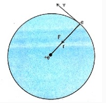
    Electron revolving around nucleus in hydrogen atom

    The force of attraction between electron and nucleus is given by Coulomb's law:

    \(\mathbf{F}=\frac{1}{4 \pi \varepsilon_{\theta}} \frac{e^{2}}{r^{2}}\)

    The centripetal force is given by \(\frac{\mathrm{mv}^{2}}{\mathrm{r}}\)

    \(\therefore\) Centripetal force \(=\) Electrostatic force of attraction.

    \(\frac{m v^{2}}{r}=\frac{1}{\pi \varepsilon_{0}} \frac{e^{2}}{r^{2}}\)

    Postulate 2:

    The electron revolves around the nucleus only in those orbits for which the angular momentum is equal to an integral multiple of \(\frac{h}{2 \pi},\) where \(h\) is Planck's constant. These orbits are called stable or stationary (or permitted or quantized or Bohr orbits) and electron does not radiate energy whole revolving in these orbits i.e. its energy remains constant and hence stability of atomic structure.

    Angular momentum \(=\mathrm{I} \omega\)

    Where I is moment of inertia of electron about its axis of revolution and \(\omega\) is angular velocity given by \(\omega=\frac{\mathrm{v}}{\mathrm{c}}\)

    Angular momentum \(=\mathrm{I} \omega=\mathrm{mr}^{2}\left(\frac{\mathrm{v}}{\mathrm{r}}\right)=\mathrm{mvr}\)

    By \(2^{\text {nd }}\) postulate, angular momentum \(=\mathrm{n} \frac{\mathrm{h}}{2 \pi}\)

    \(\therefore \mathrm{mvr}=\mathrm{n} \frac{\mathrm{h}}{2 \pi}\)

    Where \(\mathbf{n}=1,2,3,4, \dots\)

    That is electrons revolve in only those orbits that satisfies the equation. The integer 'n' is called principal quantum number. It also designates the orbit number.

    What is minimum angular momentum of electron in hydrogen atom?

    Postulate 3:

    When electron jumps from orbit of higher energy to an orbit of lower energy, it radiates energy in the form of quanta or photons. The energy of emitted photon is equal to the difference between energies of two orbits in which transition is taking place.

    Suppose an electron from \(\mathrm{n}^{\text {th }}\) higher orbit, jumps to \(\mathrm{p}^{\text {th }}\) lower orbit. Each \(\mathrm{E}_{\mathrm{n}}\) and \(\mathrm{E}_{\mathrm{p}}\) be the energies of electron in \(\mathrm{n}^{\text {th }}\) and \(\mathrm{p}^{\text {th }}\) orbit respectively, then

    Energy radiated \(=\mathrm{E}_{\mathrm{n}}-\mathrm{E}_{\mathrm{p}}\)

    According to Planck's quantum theory, energy is radiated in the form of packets or quanta, with each quanta having energy equal to hu; where 'h' is Planck's constant and 'U' is the frequency of emitted radiation.

    Energy radiated \(=h v\)

    An electron does not radiate energy while revolving in stable orbit but it does so only when it jumps from higher orbit to lower orbit.


  • Question 5
    1 / -0

    A long solenoid with 10 turns/cm and a radius of 7 cm carries a current of 20 / π mA. A current ii exists in a straight conductor located along central axis of the solenoid. What is the net magnetic field at a point inside the solenoid where the net magnetic field makes an angle 45o with axial direction ?

    Solution
    Because of net magnetic field inside a solenoid making an angle of \(45^{\circ}\) with axial direction, It is only possible when magnetic field due to solenoid and wire having same magnitude and perpendicular to each other
    \(\mathrm{B}_{\mathrm{net}}=\sqrt{2} \mathrm{B}_{\text {solenoid }}=\sqrt{2} \mu_{0} \mathrm{ni}=11.3 \mu \mathrm{T}\)
    KEY CONCEPTS
    Examples on Magnetic field due to long solenoid
    Apply Ampère's law, to the rectangular Amperian loop
    . Magnetic field inside: strong, uniform, directed along axis. . Magnetic field outside: negligibly weak. Number of turns per unit length: \(n\) Total current through Amperian loop: \(\mathrm{Ic}=\) nla ( 1 is the current in the wire). Ampere's law applied to rectangular loop: \(\mathrm{Ba}=\mu_{0}\) nla Magnetic field inside: \(\mathrm{B}=\mu_{0} \mathrm{nl}\)
    Examples on Magnetic field due to a solenoid
    (i) Find the number of turns per unit length in a coil.
    (ii) Find Magnetic Field inside the solenoid using Biot-Savart Law from every ring/circle of the coil.
    Example
    A long solenoid has 200 turns per \(\mathrm{cm}\) and carries a current of \(2.5 \mathrm{A}\). The magnetic field at its centre is
    Solution
    \(B=\mu_{0} n i=4 \pi \times 10^{-7} \times \frac{200}{10^{-2}} \times 2.5=6.28 \times 10^{-2} W b / m^{2}\)
    Magnetic field of a long solenoid Apply Ampère's law, to the rectangular Amperian loop
    . Magnetic field inside: strong, uniform, directed along axis. \(\cdot\) Magnetic field outside: negligibly weak.
    Number of turns per unit length: n.
    . Total current through Amperian loop: \(\mathrm{I}_{\mathrm{C}}=\) nla (I is the current in the wire). Ampère's law applied to rectangular loop: \(\mathrm{Ba}=\mu_{0}\) nla Magnetic field inside: \(\mathrm{B}=\mu_{0} \mathrm{nl}\)
  • Question 6
    1 / -0

    A disc is rotating with an angular velocity ω0. A constant retarding torque is applied on it to stop the disc. The angular velocity becomes ω0 /2 after n rotations. How many more rotations will it make before coming to rest ?

    Solution
    Retarding torque is constant. Therefore, angular retardation say a will also be constant. applying
    \(\omega^{2}=\omega_{0}^{2}-2 \alpha \theta\)
    we get,
    \(\left(\frac{\omega_{0}}{2}\right)^{2}=\omega_{0}^{2}-2 \alpha \theta_{1}\)
    and \(0=\left(\frac{\omega_{0}}{2}\right)^{2}-2 \alpha \theta_{2}\)
    Solving \(n\) and \(2 n,\) we get
    \(\theta_{2}=\frac{\theta_{1}}{3}\)
    Therefore, the disc will make \(\frac{\mathrm{n}}{3}\) more rotation before coming to rest.
  • Question 7
    1 / -0
    Direction: A voltage source \(V=V_{0} \sin (100 t)\) is connected to a black box in which there can he either one element out of \(L, C, R\) or any two of them connected in series.
    At steady state the variation of current in the circuit and the source voltage are plotted together with time, using an oscilloscope, as shown.
    The element(s) present in black box is/are
    Solution

  • Question 8
    1 / -0

    In the figure shown the current flowing through 2 R is

    Solution

    In figure all resistance are connected in parallel. So \(\mathrm{R}_{\mathrm{eq}}=\frac{2 \mathrm{R} \times \mathrm{R} / 2}{2 \mathrm{R}+\mathrm{R} / 2}\) and current in all resistance flow from positive terminal of battery (means \(\mathrm{A}\) end) to negative terminal of battery (means \(\mathrm{B}\) end) as shown in the diagram.

    KEY CONCEPTS

    Series/Parallel grouping of resisters Resistors in Series and in Parallel

    \[
    \mathrm{R}=\mathrm{R}_{1}+\mathrm{R}_{2}
    \]
    for resistors in series.
    This result can be readily extended to a network consisting of n resistors in series.
    \[
    R=R_{1}+R_{2} \ldots \ldots+R_{n}
    \]
    \(\frac{1}{R}=\frac{1}{R_{1}}+\frac{1}{R^{2}}\) for resistors in parallel
    Circuit Analysis
    Here the potential applied across the circuit is \(12 \mathrm{V}, \mathrm{I}_{\mathrm{T}}\) is the total current flowing in the circuit and \(\mathrm{I}_{\mathrm{T}}=\mathrm{I}_{1}+\mathrm{I}_{2}\)
    Also as the resistor of \(12 \Omega\) are in parallel the voltage across both of them is equal, also the resistances are equal which means \(\mathbf{I}_{1}=\mathbf{I}_{2}\)
    Also the total resistance across the circuit is 12 ohm and thus \(\mathrm{I}_{\mathrm{T}}=1\) ampere.
    Now we can find the voltage across 12 ohm resistance, which is 6 volts each.
    Examples on Resistors in Parallel
    I. Find the total emf applied across the circuit
    in. Now the current gets distributed ie; \(I_{e q}=I_{1}+I_{2}+\ldots+I_{n}\) and the voltage across all the loops remains the same as applied voltage.
    ili. Applying the Ohm's law, we get \(\frac{1}{R_{e q}}=\frac{1}{R_{1}}+\frac{1}{R_{2}}+\ldots+\frac{1}{R_{n}}\)
    Example
    The equivalent resistance between \(A\) and \(B\) in the circuit shown will be:
    Solution:
    In the circuit, by means of symmetry, the point \(C\) is at zero potential. So the equivalent circuit can be drawn as
    \(R_{e q}=\frac{\frac{8 r}{3} \times 2 r}{\frac{b}{3}+2 r}=\frac{8}{7} r\)
    Grouping of Resistors Resistors in Series and in Parallel
    Resistors are probably the most commonly occurring components in electronic circuits. Practical circuits often contain very complicated combinations of resistors. It is, therefore, useful to have a set of rules for finding the equivalent resistance of some general arrangement of resistors. It turns out that we can always find the equivalent resistance by repeated application of two simple rules. These rules relate to resistors connected in series and in parallel.
    Consider two resistors connected in series, as shown in fig. It is clear that the same current I flows through both resistors. For, if this were not the case, charge would build up in one or the other resistors, which would not correspond to a steady-state situation (thus violating the fundamental assumption of this section). Suppose that the potential drop from point \(B\) to point \(A\) is \(V\). This drop is the sum of the potential drops \(V_{1}\) and \(V_{2}\) across the two resistors \(R_{1}\) and \(R_{2}\), respectively. Thus,
    \(\mathbf{V}=\mathbf{V}_{1}+\mathbf{V}_{2}\)
    According to Ohm's law, the equivalent resistance \(R_{\mathrm{eq}}\) between \(\mathrm{B}\) and \(\mathrm{A}\) is the ratio of the potential drop \(\mathrm{V}\) across points and the current I which flows between them. Thus,
    \(\mathrm{R}_{\mathrm{eq}}=\frac{\mathrm{v}}{\mathrm{I}}=\frac{\mathrm{v}_{1}+\mathrm{V}_{2}}{\mathrm{I}}=\frac{\mathrm{v}_{1}}{\mathrm{I}}+\frac{\mathrm{v}_{2}}{\mathrm{I}}\)
    Giving \(R_{e q}=R_{1}+R_{2}\)
    Here, we have made use of the fact that the current I is common to all three resistors. Hence, the rule is The equivalent resistance of two resistors connected in series is the sum of the individual resistances.For \(\mathrm{N}\) resistors connected in series, eg generalizes to \(\mathbf{R}_{\mathrm{eq}}=\sum_{i=1}^{N} \mathbf{R}_{i}\)
    Consider two resistors connected in parallel, as shown in fig. It is clear, from the figure, that the potential drop \(V\) across the two resistors is the same. In general, however, the currents \(\mathrm{I}_{1}\) and \(\mathrm{I}_{2}\). Which flow through resistors \(\mathrm{R}_{1}\) and \(\mathrm{R}_{2}\), respectively, are different. According to Ohm's law, the equivalent resistance \(\mathrm{R}_{\mathrm{eq}}\) between \(\mathrm{B}\) and \(\mathrm{A}\) is the ratio of the potential drop \(\mathrm{V}\) across these points and the current I which flows between them. This current must equal the sum of the currents \(\mathbf{I}_{1}\) and \(\mathbf{I}_{2}\) flowing through the two resistors, otherwise charge would build up at one or both of the junctions in the circuit. Thus,
    \(\mathbf{I}=\mathbf{I}_{1}+\mathbf{I}_{2}\)
    It follows that
    \(\frac{1}{R_{e q}}=\frac{I}{V}=\frac{I_{1}+L_{2}}{V}=\frac{I_{1}}{V}+\frac{L_{2}}{V}\)
    Giving
    \(\frac{1}{R_{e q}}=\frac{1}{R_{1}}+\frac{1}{R_{2}}\)
    Here, we have made use of the fact that the potential drop \(V\) is common to all three resistors. Clearly, the rule is
    The reciprocal of the equivalent resistance of two resistances connected in parallel is the sum of the reciprocals of the individual resistances.
    For \(\mathrm{N}\) resistors connected in parallel, eq generalizes.
    \(\frac{1}{\mathrm{R}_{\mathrm{eq}}}=\sum_{\mathrm{i}=1}^{\mathrm{N}}\left(\frac{1}{\mathrm{R}_{\mathrm{i}}}\right)\)
  • Question 9
    1 / -0

    A unknown circuit element X is connected in series with a resistor R to an AC source. If VAB=VAC (rms value). than X is-

    Solution
    EXPLANATION
    At resonance
    \(\mathrm{V}_{\mathrm{BC}}=0\)
    \(\therefore \mathrm{V}_{\mathrm{AB}}\) become equal to \(\mathrm{V}_{\mathrm{AC}}\)
    KEY CONCEPTS
    RLC circuit Introduction: An RLC circuit (or LCR circuit or CRL circuit or RCL circuit) is an electrical circuit consisting of a resistor, an inductor, and a capacitor, connected in series or in parallel. The RLC part of the name is due to those letters being the usual electrical symbols for resistance, inductance and capacitance respectively. The circuit forms a harmonic oscillator for current and will resonate in a similar way as an LC circuit will. The main difference that the presence of the resistor makes is that any oscillation induced in the circuit will die away over time if it is not kept going by a source. This effect of the resistor is called damping. The presence of the resistance also reduces the peak resonant frequency somewhat. Some resistance is unavoidable in real circuits, even if a resistor is not specifically included as a component. An ideal, pure LC circuit is an abstraction for the purpose of theory. Resonance: resonance frequency, f0, angular frequency,
    Resonance
    An important property of this circuit is its ability to resonate at a specific frequency, the resonance frequency, \(\int_{0}\). Frequencies are measured in units of hertz. In this article, however, angular frequency, \(\omega_{0}\), is used which is more mathematically convenient. This is measured in radians per second. They are related to each other by a simple proportion,
    \(\omega_{0}=2 \pi \int_{0}\)
    Natural frequency
    \(\omega_{0}=\frac{1}{\sqrt{\mathrm{LC}}}\)
    Damping
    \(\mathbf{s}=\frac{\alpha}{\omega_{0}}\)
    Bandwidth
    \(\Delta \omega=\omega_{2}-\omega_{1}\)
    \(\Delta \omega=2 \mathrm{a}\)
    \(\mathbf{F}_{\mathbf{b}}=\frac{\Delta \omega}{\omega_{0}}\)
    Q factor
    \(Q=\frac{1}{F_{b}}=\frac{\omega_{B}}{\Delta \omega}\)
    \(Q=\frac{1}{\omega_{0} R C}=\frac{\omega_{0} L}{R}\)
    Series RLC circuit
    \(\alpha=\frac{\mathrm{R}}{2 \mathrm{L}}\) and \(\omega_{0}=\frac{1}{\sqrt{\mathrm{LC}}}\)
    \(\mathrm{s}=\frac{\alpha}{\omega_{0}}\)
    \(\mathrm{s}=\frac{\mathrm{R}}{2} \sqrt{\frac{\mathrm{C}}{\mathrm{L}}}\)
    Parallel RLC circuit
    \(\alpha=\frac{1}{2 \mathrm{RC}}\)
    \(\mathrm{s}=\frac{1}{2 \mathrm{R}} \sqrt{\frac{\mathrm{L}}{\mathrm{C}}}\)
    Examples on LCR Circuits A RLC circuit is an electrical circuit consisting of a resistor (R), an inductor (L), and a capacitor (C), connected in series or in parallel. The name of the circuit is derived from the letters that are used to denote the constituent components of this circuit, where the sequence of the components may vary from RLC.
    The circuit forms a harmonic oscillator for current, and resonates in a similar way as an LC circuit. Introducing the resistor increases the decay of these oscillations, which is also known as damping. The resistor also reduces the peak resonant frequency. Some resistance is unavoidable in real circuits even if a resistor is not specifically included as a component. An ideal, pure LC circuit is an abstraction used in theoretical considerations.
    LCR Circuits Introduction: An RLC circuit (or LCR circuit or CRL circuit or RCL circuit) is an electrical circuit consisting of a resistor, an inductor, and a capacitor, connected in series or in parallel. The RLC part of the name is due to those letters being the usual electrical symbols for resistance, inductance and capacitance respectively. The circuit forms a harmonic oscillator for current and will resonate in a similar way as an LC circuit will. The main difference that the presence of the resistor makes is that any oscillation induced in the circuit will die away over time if it is not kept going by a source. This effect of the resistor is called damping. The presence of the resistance also reduces the peak resonant frequency somewhat. Some resistance is unavoidable in real circuits, even if a resistor is not specifically included as a component. An ideal, pure LC circuit is an abstraction for the purpose of theory. Resonance: resonance frequency, f0, angular frequency.
    Resonance
    An important property of this circuit is its ability to resonate at a specific frequency, the resonance frequency, \(\int_{0}\). Frequencies are measured in units of hertz. In this article, however, angular frequency, \(\omega_{0}\), is used which is more mathematically convenient. This is measured in radians per second. They are related to each other by a simple proportion,
    \(\omega_{0}=2 \pi\left[_{0}\right.\)
    Natural frequency
    \(\omega_{0}=\frac{1}{\sqrt{\mathrm{LC}}}\)
    Damping
    \(\zeta=\frac{\alpha}{\omega_{0}}\)
    Bandwidth
    \(\Delta \omega=\omega_{2}-\omega_{1}\)
    \(\Delta \omega=2 \alpha\)
    \(\mathbf{F}_{\mathbf{b}}=\frac{\Delta \omega}{\omega_{0}}\)
    Q factor
    \(Q=\frac{1}{P_{b}}=\frac{\omega_{i}}{\Delta \omega}\)
    \(Q=\frac{1}{\omega_{0} R C}=\frac{\omega_{0} L}{R}\)
    Series RLC circuit
    \(\alpha=\frac{R}{2 L}\) and \(\omega_{0}=\frac{1}{\sqrt{L C}}\)
    \(\mathrm{s}=\frac{\alpha}{\omega_{0}}\)
    \(\mathrm{s}=\frac{\mathrm{R}}{2} \sqrt{\frac{\mathrm{C}}{\mathrm{L}}}\)
    Parallel RLC circuit
    \(\alpha=\frac{1}{2 R C}\)
    \(\zeta=\frac{1}{2 R} \sqrt{\frac{L}{C}}\)
    Resonance of series LCR circuit Damping and the Natural Response in RLC Circuits
    Consider a series RLC circuit (one that has a resistor, an inductor and a capacitor) with a constant driving electro-motive force
    (emf) E. The current equation for the circuit is
    \(L \frac{d i}{d t}+R i+\frac{1}{C} \int i d t=E\)
    This is equivalent: \(L \frac{d i}{d t}+R i+\frac{1}{C} q=E\)
    Differentiating, we have
    \(L \frac{d^{2} i}{d t^{2}}+R \frac{d i}{d t}+\frac{1}{C} i=0\)
    This is a second order linear homogeneous equation. Its corresponding auxiliary equation is \(L m^{2}+R m+\frac{1}{C}=0\) with roots \(m_{1}=\frac{-R}{2 L}+\frac{\sqrt{\left(R^{2}-\frac{4 L}{C}\right)}}{2 L}\)
    \(=-\alpha+\sqrt{\alpha^{2}-\omega_{0}^{2}}\)
    \(m_{2}=\frac{-R}{2 L}-\frac{\sqrt{\left(R^{2}-\frac{4 L}{C}\right)}}{2 L}\)
    \(=-\alpha-\sqrt{\alpha^{2}-\omega_{0}^{2}}\)
    Now,
    \(\alpha=\frac{R}{2 L}\) is called the damping coefficient of the circuit
    \(\omega_{0}=\sqrt{\frac{1}{L C}}\) is the resonant frequency of the circuit
    \(m_{1}\) and \(m_{2}\) are called the natural frequencies of the circuit.
  • Question 10
    1 / -0

    The equivalent capacitance of the combination of three capacitors, each of capacitance C shown in figure between points A and B is

    Solution
    In the arrangement shown both plates of capacitors \(C_{3}\) are joined to point \(B\). Hence, it does not act as a capacitor and is superfluous. Now \(C_{1}\) and \(C_{2}\) are in parallel, hence \(C_{A B}=C_{1}+C_{2}=C+C=2 C\)
    KEY CONCEPTS
    Capacitors in Series \& Parallel Capacitors in Series
    \(\frac{1}{c}=\frac{1}{c_{1}}+\frac{1}{c_{2}}+\frac{1}{c_{3}}+\ldots \ldots .\)
    Capacitors in Parallel
    \(\mathrm{C}=\mathrm{C}_{1}+\mathrm{C}_{2}+\mathrm{C}_{3}+\ldots\)
    Combination of Capacitors Capacitors in Series and in Parallel
    Capacitors are one of the standard components in electronic circuits. Moreover, complicated combinations of capacitors often occur in practical circuits. It is, therefore, useful to have a set of rules for finding the equivalent capacitance of some general arrangement of capacitors. It turns out that we can always find the equivalent capacitance by repeated application of two simple rules. These rules related to capacitors connected in series and in parallel.
    Consider two capacitors connected in parallel: i.e., with the positively charged plates connected to a common "input" wire, and the negatively charged plates attached to a common "output" wire see Fig. What is the equivalent capacitance between the input and output wires? In this case, the potential difference \(V\) across the two capacitors is the same, and is equal to the potential difference between the input and output wires. The total charge \(Q\), however, stored in the two capacitors is divided between the capacitors, since it must distribute itself such that the voltage across the two is the same. since the capacitors may have different capacitance, \(C_{1}\) and \(C_{2}\), the charges \(Q_{1}\) and \(Q_{2}\) may also be different. The equivalent capacitance \(C_{\mathrm{eq}}\) of the pair of capacitors is simply the ratio \(Q / V\), where \(Q=Q_{1}+Q_{2}\) is the total stored charge. It follows that
    \(C_{e q}=\frac{Q}{V}=\frac{Q_{1}+Q_{2}}{V}=\frac{Q_{1}}{V}+\frac{Q_{2}}{V}\)
    Giving \(C_{e q}=C_{1}+C_{2}\)
    Here, we have made use of the fact that the voltage \(V\) is common to all three capacitors. Thus, the rule is:
    The equivalent capacitance of two capacitors connected in parallel is the sum of the individual capacitance.
    For \(\mathrm{N}\) capacitors connected in parallel, Eq. generalizes to \(C_{e q}=\sum_{i=1}^{N} C_{i}\)
    Consider two capacitors connected in series: i.e., in a line such that the positive plate of one is attached to the negative plate of the other-
    -see Fig. In fact, let us suppose that the positive plate of capacitor 1 is connected to the "input" wire, the negative plate of capacitor 1 is connected to the positive plate of capacitor \(2,\) and the negative plate of capacitor 2 is connected to the "output" wire. What is the equivalent capacitance between the input and output wires? In this case, it is important to realize that the charge \(Q\) stored in the two capacitors is the same. This is most easily seen by considering the "internal" plates: i.e., the negative plate of capacitor 1 , and the positive plate of capacitor 2 . These plates are physically disconnected from the rest of the circuit, so the total charge on them must remain constant Assuming, as seems reasonable, that these plates carry zero charge when zero potential difference is applied across the two capacitors, it follows that in the presence of a non-zero potential difference the charge \(+Q\) on the positive plate of capacitor 2 must be balanced by an equal and opposite charge \(-Q\) on the negative plate of capacitor \(1 .\) since the negative plate of capacitor 1 carries a charge \(-\mathrm{Q}\), the positive plate must carry a charge \(+\mathrm{Q}\). Likewise, since the positive plate of capacitor 2 carries a charge \(+\mathrm{Q}\) the negative plate must carry a charge - \(Q\). The net result is that both capacitors possess the same stored charge \(Q\). The potential
    drops, \(V_{1}\) and \(V_{2}\), across the two capacitors are, in general, different. However, the sum of these drops equals the total potential drop \(V\) applied across the input and output wires: i.e., \(V=V_{1}+V_{2}\). The equivalent capacitance of the pair of capacitors is again \(C_{e q}=Q / V\). Thus
    \(\frac{1}{C_{n}}=\frac{V}{Q}=\frac{V_{1}+V_{2}}{Q}=\frac{V_{1}}{Q}+\frac{V_{2}}{Q}\)
    Giving \(, \frac{1}{C_{n q}}=\frac{1}{C_{1}}+\frac{1}{C_{2}}\)
    Here, we have made use of the fact that the charge \(Q\) is common to all three capacitors. Hence, the rule is:
    The reciprocal of the equivalent capacitance of two capacitors connected in series is the sum of the reciprocals of the individual capacitance
    For \(\mathrm{N}\) capacitors connected in series, Eq. generalizes to
    \(\frac{1}{C_{m}}=\sum_{i=1}^{N}\left(\frac{1}{C_{i}}\right)\)
Self Studies
User
Question Analysis
  • Correct -

  • Wrong -

  • Skipped -

My Perfomance
  • Score

    -

    out of -
  • Rank

    -

    out of -
Re-Attempt Weekly Quiz Competition
Self Studies Get latest Exam Updates
& Study Material Alerts!
No, Thanks
Self Studies
Click on Allow to receive notifications
Allow Notification
Self Studies
Self Studies Self Studies
To enable notifications follow this 2 steps:
  • First Click on Secure Icon Self Studies
  • Second click on the toggle icon
Allow Notification
Get latest Exam Updates & FREE Study Material Alerts!
Self Studies ×
Open Now